|
LabGuy's World: NBTV - 32 Line BIG Televisor Project
[HOME] [ELECTRONICS PROJECTS] Let's build a "big screen" Televisor, shall we? 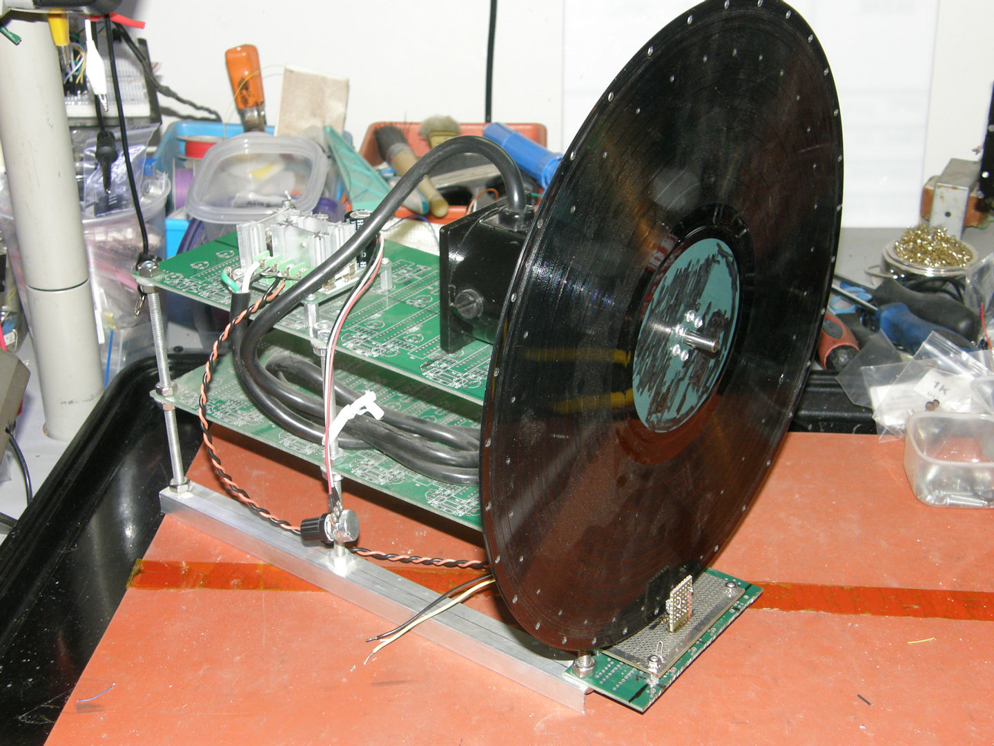
The NBTV - 32 Line BIG Televisor Project Let's construct a new 32 line NBTV (Narrow Band Television) televisor with a larger size than my previous Mindsets kit televisor or my upcoming Tiny Televisor. This one will use a 12 inch LP as the Nipkow disk along with a large DC motor to avoid being under powered. This baby will have an enormous, almost one inch tall, image window. Woo hoo! I purchased this DC motor from a company in Chicago based on a recommendation by a famous video engineer by the name of Mike Talent. The article I referenced was quite old already at the time. This darned motor ended up costing me over two hundred dollars. So much for taking advice from someone who makes three times as much income as I do. Putting all that aside, it is a very nice motor for the job. (It better be!) With the square flanges tapped on the edges for machine screws, it was very easy to mount as compared with some of the round body motors I used in the past. (See: The Goldmark 1, CBS color TV for instance) If you are interested, this motor is a standard size and is still available, at the time of this writing (20200817), for $220. Model number: 051-206-4005, manufactured by: [Bison Gear & Engineering Corp.] It is almost certain that you can scrounge a DC motor, of equivalent size and power for a much lower cost, from scrapping or scrounging. (Which is more fun anyway.) It might be a tad big, but howzabout a DC motor from a discarded tread mill? Can you say, "Three foot diameter Nipkow disk?" I knew that you dould. 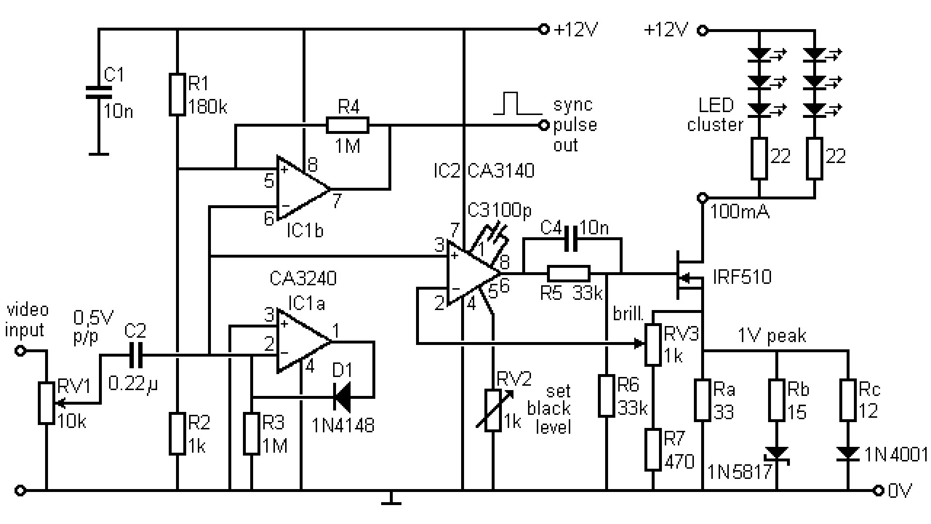
[The NBTV - 32 Line Televisor Reference design] Please, click the title under the schematics above to go to the NBTV web site and seriously consider becoming a paying member to help keep the art and this hobby alive. After a false start, I settled on the reference circuits found at the NBTV web site. NBTV stands for Narrow Band Tele Vision. The bandwidth of NBTV is just a bit over 10KHz. So, audio bandwidth parts will suffice. Above, are the two schematics from which I (re)started this project. My earlier, far more complex, system was just too full of bugs to justify. The less said about that, the better. 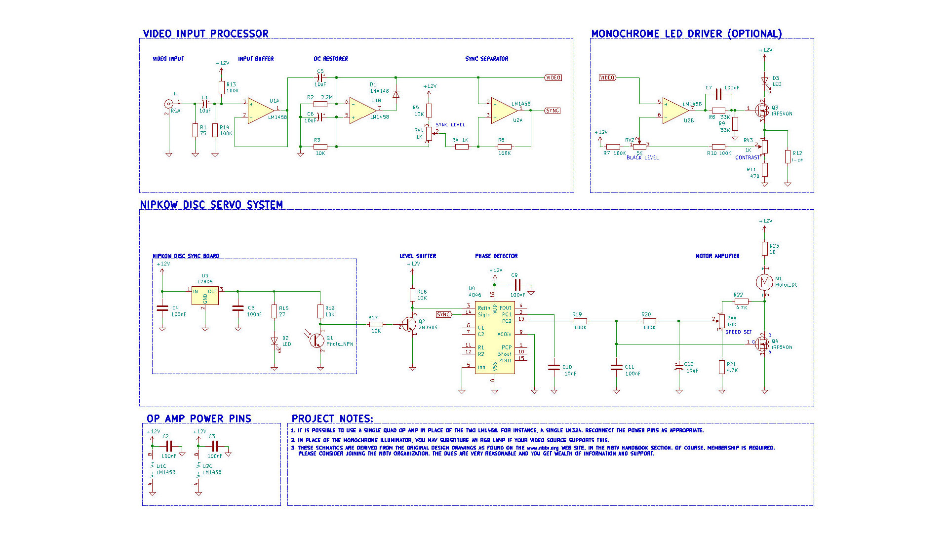
Labguy's first order version of the NBTV reference design Let's quickly go through the schematic shown above, starting with the video input processor in the upper left. Video enters the project through an RCA jack. In this case, the video is terminated in a 75Ω. For projects that use audio equipment as the signal source, change this resistor to 10KΩ. The signal is AC coupled from there through a 10μF capacitor to the LM1458 opamp configured as a unity gain buffer. Next the signal is once again AC coupled through a second 10μF capacitor to a DC restorer circuit. From there, the signal goes to the next opamp which is configured as a comparator for slicing and separating composite sync from the video signal.
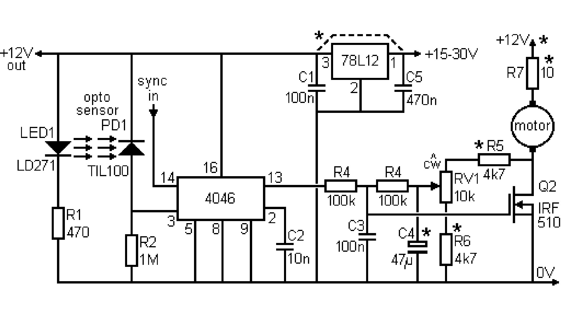
The heart of the Nipkow disc servo circuit is the CD4046 Phase Locked Loop IC. In this case only one of two possible phase detectors is being used. This is phase detector 2. It compares the relative phase of two rising edges, independent of the duty cycle of the pulse sources. Separated sync is fed into the CD40436 via pin 14 and wheel servo pulses go into pin 3. The phase control voltage coming out of pin 13 is sent through a low pass filter (100K / 100nF) and summed with a voltage derived from the motor current. This composite DC control signal is passed to the gate electrode of the power FET, Q4, an IRF540N. This FET is the motor drive amplifier. That is pretty much all that makes up a classic Baird style televisor. His system was brilliantly simple in its execution. The man was a friggin' genius! (Before you write me an angry email, clearly this is not an actual John Logie Baird design. His work was done all in vacuum tubes. I am implying that the basic block diagram is essentially identical to Baird's work of the 1920s and 1930s. These electronics are of relatively modern design and are the best the 1970s had to offer. So, technically, still relatively antique!) 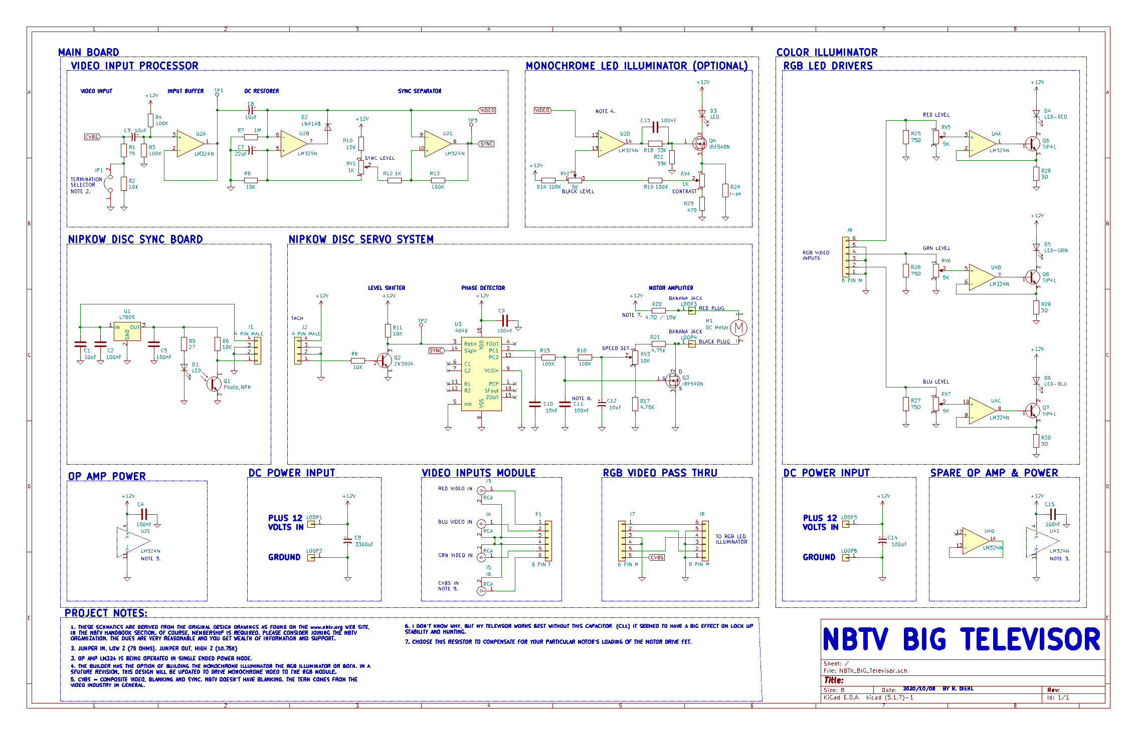
Big Televisor Schematic - As constructed The schematic above is of the completed color televisor. The monochrome light source was not implimented. But its schematic diagram is included here for completeness. You will note the triple LED driver on the far right side. My video generator puts out separate signals, sync (composite monchrome video) and red, green and blue video signals. As built, this color televisor can not display a BW composite video picture. A later update for this system is in the works to make it possible to view monochrome video on this unit. I built the unit as a series of separable modules for easy servicing. This why there are so many intermediate connectors on this schematic. In this way, if a module failed to meet the design requirement, a new one could be fabricated and plugged right in without having to rework a larger portion of the project. Finally, the opamps were changed from two LM1458Ns on the breadboard version to a single LM324N on this unit. The former being dual opamps in 8 pin DIP and the later being a quad in 14 pin DIP. Otherwise, their circuit functions and operation is identical. The servo feedback from the disk is by way of an optical interrupter. It has a high powered red LED as the light source and a phototransistor as the receiver. The light needs to be relatively bright to overcome interference from ambient room light and to have enough optical power to trip the phototransistor after passing through the fast moving sync holes. It connects to the video / servo board via a four pin connector and cable. The opto board contains its own five volt regulator. 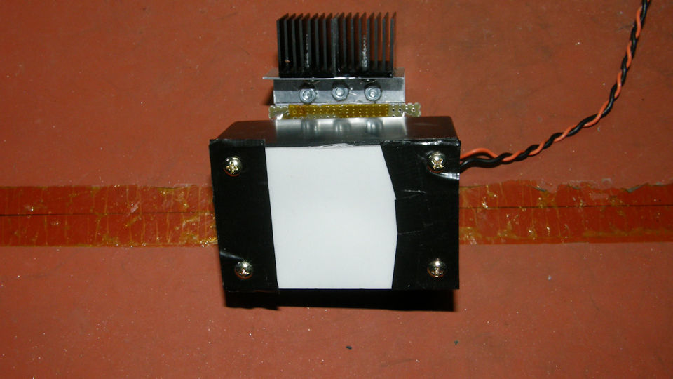
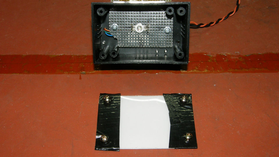
RGB LED Color Illuminator Box I did not implement the monochrome LED driver in my design. So, that circuit is untested and my schematic does not show the gamma correction diodes in the lower leg of Q3. See the NBTV schematic for that detail. Instead, I constructed a color illuminator box. This one is driven with the separate RGB drive video provided by my Aurora Designs World Converter. The absence of gamma correction in the LED drivers is allowable as the World Converter performs the gamma correction function instead - and does a superior job as compared to the multiple resistor and diode approach. The RGB signals enter the Big Televisor through RCA jacks on the video/servo board and are relayed to the illuminator via a 6 pin cable. This unit is powered by 12 volts also delivered from the video/servo board via a two pin cannector and cable. The RGB illuminator consists of a high powered, 5 watt, RGB LED intended for a track light, installed in a plastic project box with the driver electronics circuit board mounted to the rear of the box by way of short #4-40 stand offs. The LED has a heat sink pad on its rear face and this is thermally coupled to the metal ground plane of the support circuit board mounted inside the box. The driver circuits are simple voltage to current converters that provide up to 330mA to each individual LED. Needless to say, this unit is very bright. The driver transistors are dropping about 9 volts at 330mA each and they do get quite hot. You can see the heat sink I fabricated on the top of the box. The diffuser is made of transluscent white plastic sheet salvaged from an illuminator intended for use on a flat bed scanner. That illuminator was intended for scanning transparent photographic film slides or negatives. What was originally one very long strip was cut into thirds and stacked up to increase the diffusing effect to give the illuminator the flattest field of white light possible. This works very well. Making a good flat diffuser can be the hardest part of a mechanical telvision project. 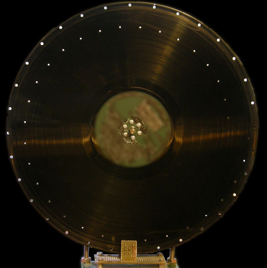
The 12 Inch Nipkow Disk The disk was once a 33-1/3 RPM long play record. I purchased six or seven old obscure records at a flea market just to sacrifice them to the Gods of mechanical television. ("Blessed be Nipkow the omnipotent! Shine down your glory on your humble servant for this honorable sacrifice. Boom chacka lacka boom chacka lacka BOOM! "). I drilled the NBTV standard pattern of scanning holes in the disk based on a template I had fabricated several years ago. That disk actually was horrible in dynamic performance and could not be used. But it can be bolted to any LP record and the holes drilled through by hand with not perfect, but relatively good, precision. There was a small error in my calculations resulting in a slightly wider image aspect ration than specified in the NBTV standard. I will (may) fix this in a future disk design. I still have plenty of old LP records!. The speed and phase detector circuit works by comparing the Line and Frame sync pulses, separated from input video, with the tachometer pule feedback from the photo interrupter sensor positioned at the rim of the scanning disk. There are 32 holes positioned around the rim, with one hole masked off to indicate the start of frame time. Which hole this is is determined experimentally at the time of servo debugging and tuning. This is because the tach sensor is positioned roughly 90 degrees from the image plane. In the photo above, the taped over hole is hidden behind the photo detector at the bottom of the disk. By blocking one of the sync holes, the pulse stream from the spinning disc is the same as the sync stream in the video. 31 sync pulses with the one missing pulse indicating the frame sync position. The phase detector has no problem locking these two streams of pulses together. 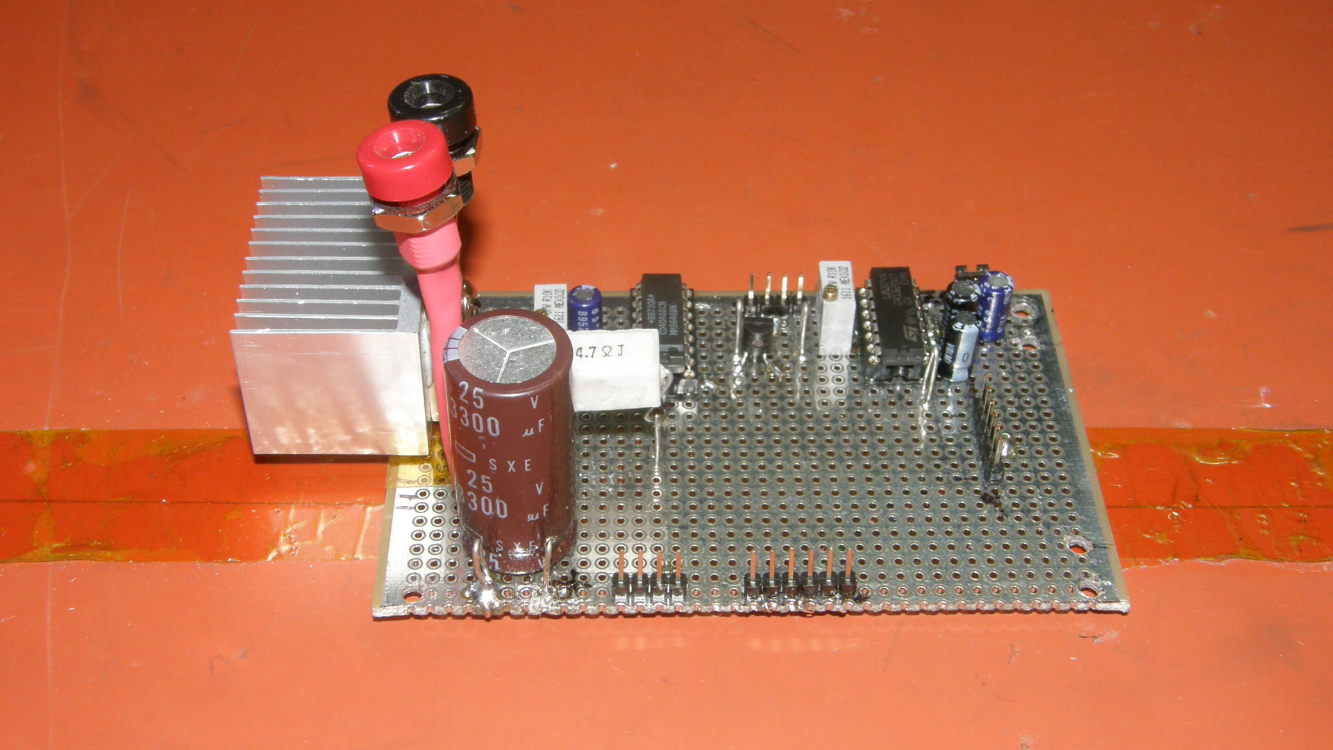
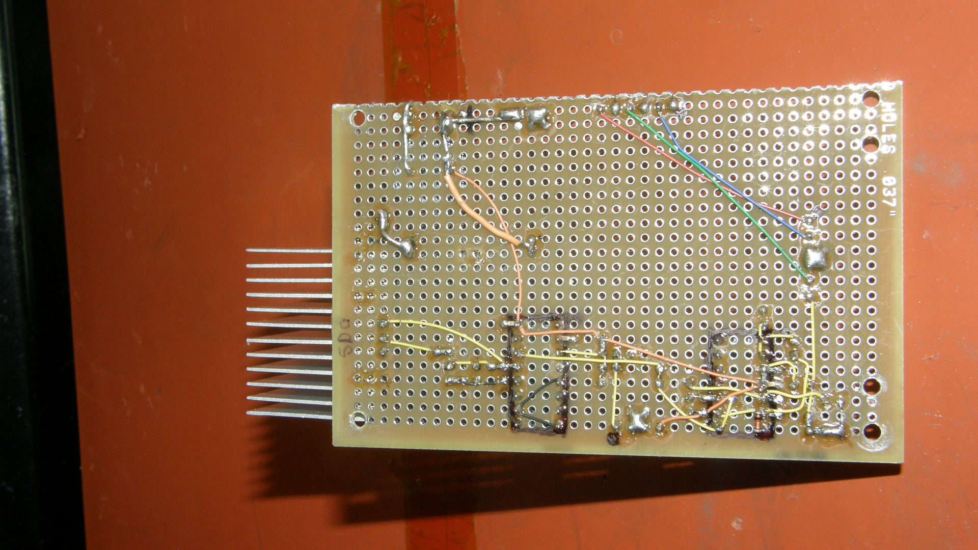
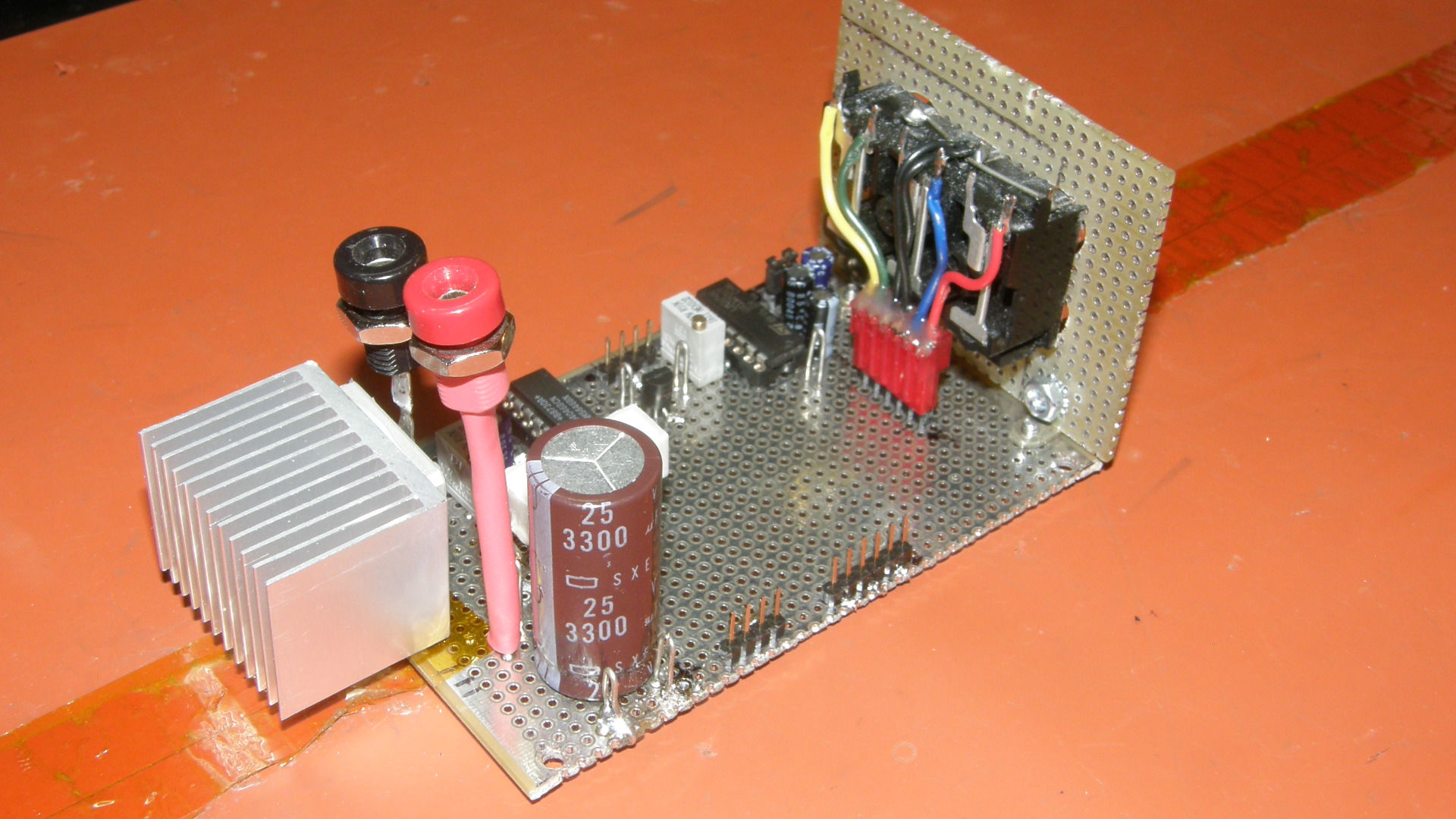
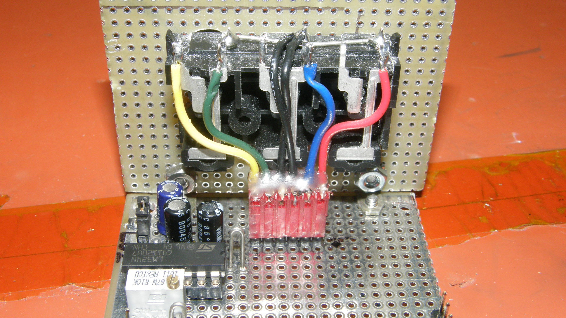

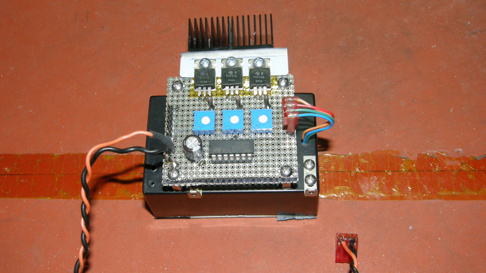
Video / Servo / Connector Board The video / servo / connector board came out very simple in the end. It was constructed with my usual mix of through hole and SMT components. Most of the passive components are 0603 size reistors and capacitors, installed on the bottom side of the PCB. The 0603 size passives (60mils by 30mils, resistors and capacitors) fit neatly between the 100 mil (1/10 inch or 2.54mm) spaced pads and holes on this type of bread board material. The two chips consist of the LM324N quad opamp and the CD4043 Phase Locked Loop. Both are standard 300 x 100 mil pin spacing DIP parts. There are only two alignment pots. One for the sync slicer theshold and the other for the motor current feedback. The input connectors are mounted to a separate PCB, placed at right angles to the main board, and connected through a six pin Molex connector to allow disassembly for repairs and modifications. All but the primary 12 volt power connections are plug in types. Power is hard soldered for higher reliabilty because of the amount of current drawn by the system. About 1.5 amps at 12 volts. That's more than I was comfortable with running though the Dupont style header pins. The motor driver FET is placed at the end of the board and equipped with a heat sink because it is doing a fair anount of work. It gets quite hot too, just like the LED drivers. Part of the heat loading is aleviated from the FET by placing a 4.7Ω, 3 watt resistor in series with the motor drive circuit. If you copy this design, you will need to experiment with this resistor value to find one that keeps the motor current inside its needed control range. Values of from 1Ω to up to 10Ω would probably be a good place to start. It also depends on how well you heat sink your transistor. 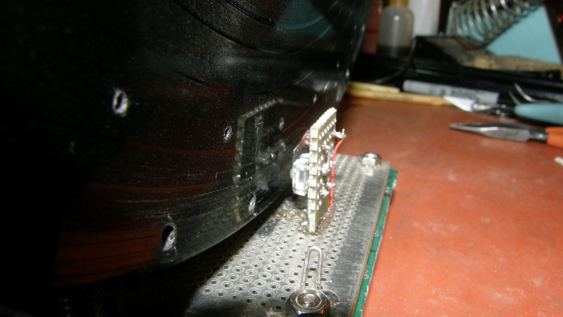
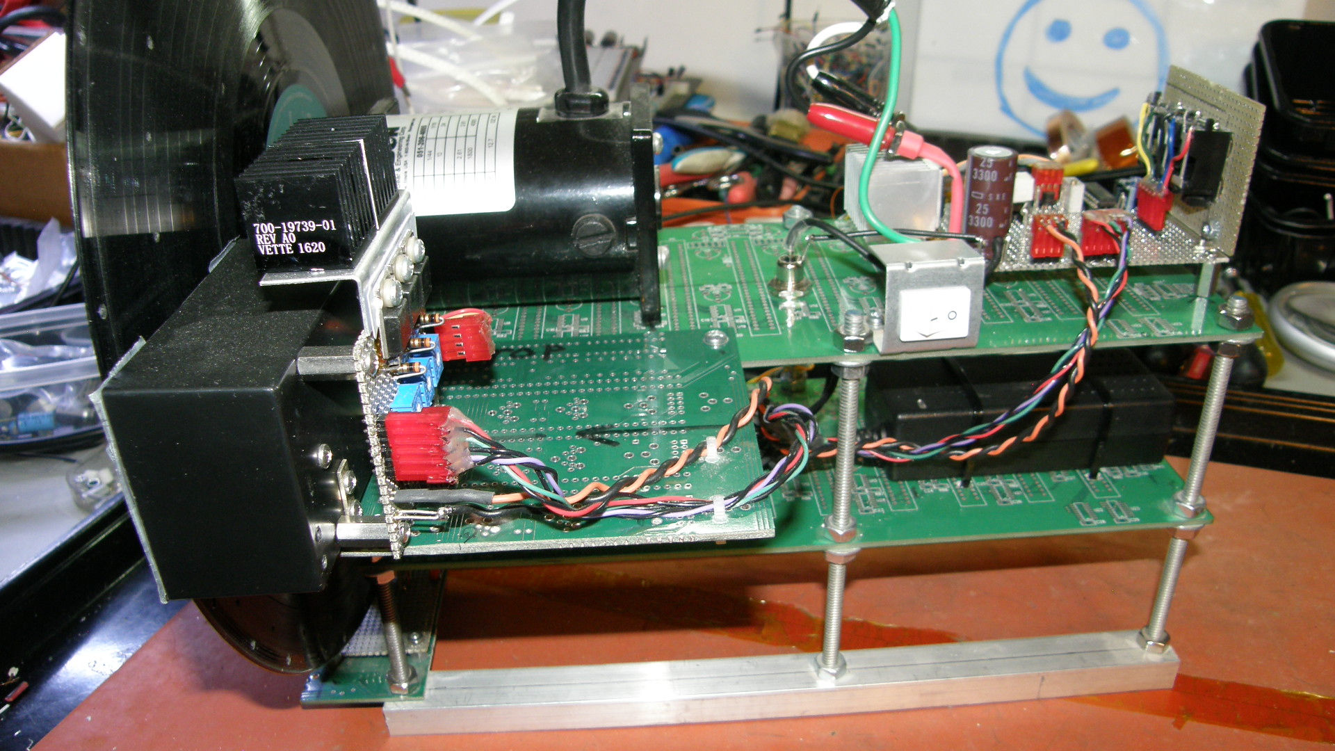
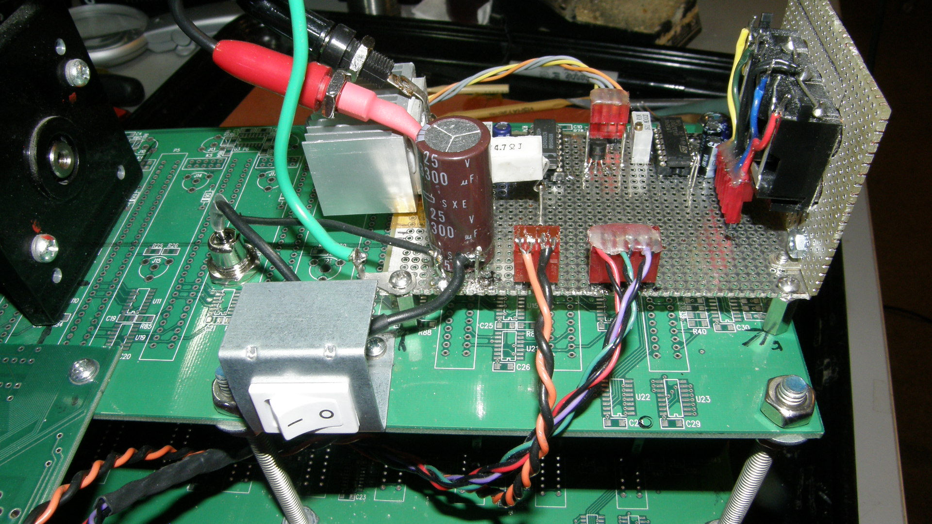
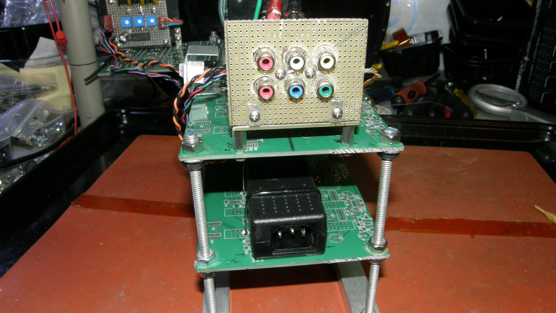
Big Televisor Final Construction Above are the final construction photos. The first is the high intensity LED on the home built photo interruptor. The Nipkow disk servo and scanning holes are in sharp detail for your examination. Picture 2 is the side view showing all of the assemblies on the unit. Photo 3 is a closer look at the mounted video / servo / connector board. You can clearly see how the motor plugs in with a pair of banana jacks and plugs. This allows easy removal of the main board for servicing when needed. The final photo shows both the input connectors and the surplus 12 volt 2 amp power supply which makes the whole unit into a stand alone self powered Televisor. 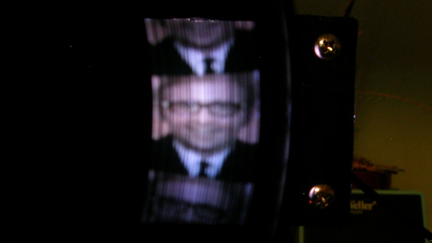

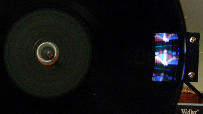
Actual Big Televisor Video Images The end result was rather respectable. The unit works well and makes very good pictures - ignoring the inaccurate line spacing pitch of the hand drilled disk. So, all in all, this was a challenging and fun project. Though it languished on a shelf for a couple of years, when I finally got down to it, the Big Televisor was completed in about four weeks. Not bad for a project of this complexity. You can see videos of this project's progress and evolution on YouTube at the links below: [NBTV "BIG" Televisor, Part 1] Project Launch, initial design begins. (13 minutes)[NBTV "BIG" Televisor, Part 2] The illuminator module. (20 minutes, 30 seconds) [NBTV "BIG" Televisor, Part 3] Project progress report. (19 minutes, 30 seconds) [NBTV "BIG" Televisor, Part 4] Another progress report. (18 minutes, 7 seconds) [NBTV "BIG" Televisor, Part 5] Success! The darned thing works! (31 minutes, 41 seconds) [NBTV "BIG" Televisor, Part 6] The BIG Televisor Completed. (13 minutes, 21 seconds) [NBTV "BIG" Televisor, Connector Problems & Solutions] (1 hour, 5 minutes) [HOME] [ELECTRONICS PROJECTS] |