LabGuy's World: The Chief, Part 2 - Low and High Voltage Power Supplies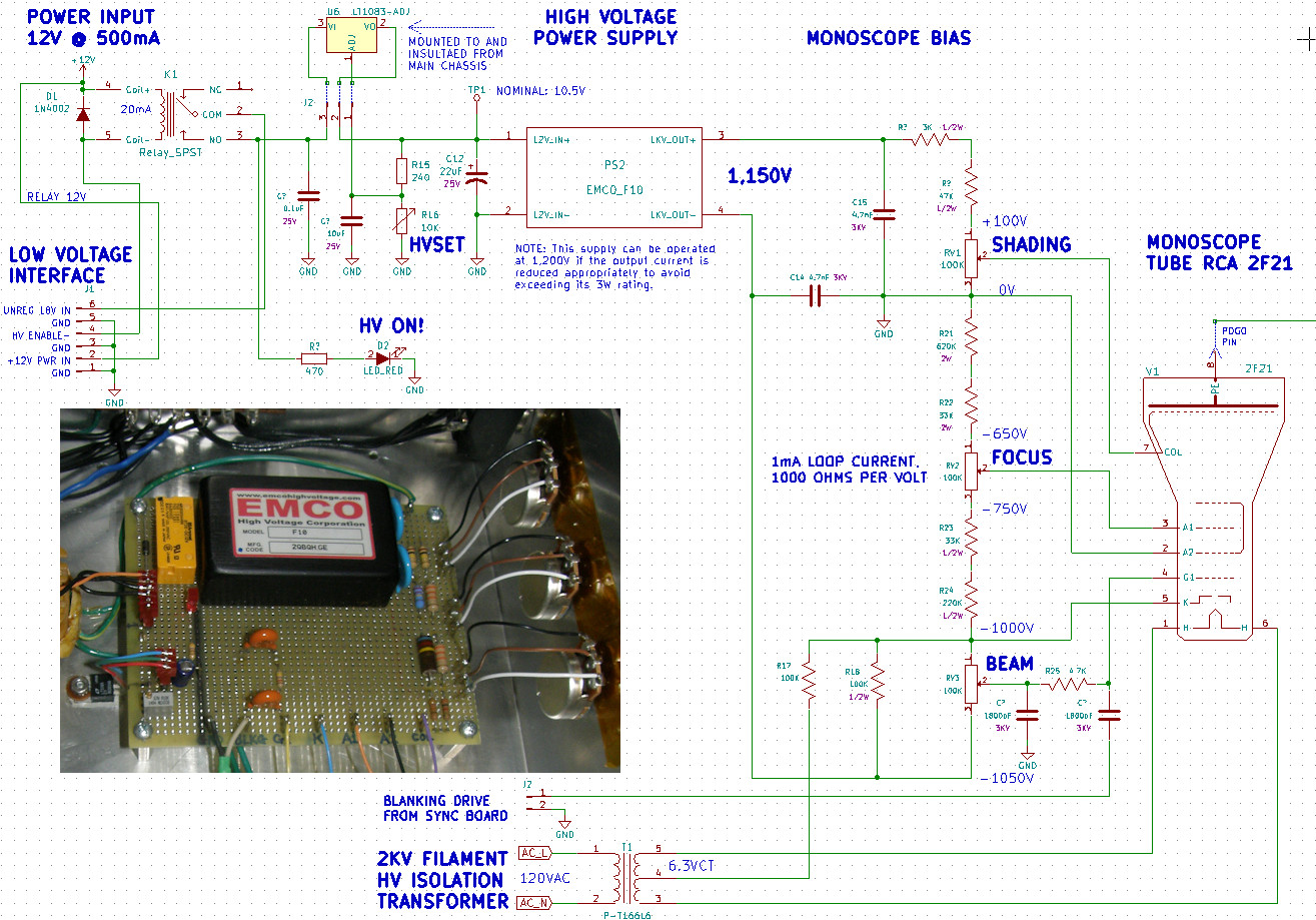
Schematic and image of the high voltage DC power supply The high voltage power supply is constructed around the Emco F10 proportional DC to DC converter. This compact module delivers a nominal one thousand volts at a maximum current of 3.33mA which is 3 watts. It can be operated at a higher output voltage, in this case 1,200 volts if one takes care to lower the load current appropriately and not exceed the 3 watt rating. The output voltage is controlled by the input voltage in a proportional manner. Increase the input and the output follows and vice versa. The unit is claimed to operate on any voltage between 0.6V and 12V. My design operates the converter with a 1mA load resulting in only 1.2 watts of dissipation. Due to inefficiency, the input power is about 5 watts. Let's look at the input side of the converter first. The activation relay is powered from the +12 volt supply. In the event of 12 volt supply failure, the relay will be disabled, the converter is shut down, and thus the monoscope picture electrode is protected from burn damage. An LT1083 adjustable voltage regulator provides the high voltage control and allows for its adjustment. The voltage regulator is heat sunk to the metal case for dissipation. Nominal 1,200 volts is achieved, under load, with an input DC voltage of approximately 11 volts. This is easily provided by the LT1083 operating on the unregulated 18V from the low voltage power supply. All connections in and out of the baord are through connector plugs or soldered wire loops. The output of the high voltage converter floats relative to system DC ground. Ground is established at a midpoint in the resistor divider chain at the bottom of the SHADING control. The electron gun is operated in the negative high voltage mode with anode #2 at ground potential and the cathode operating at -1KV. The heater filament is powered by a 6.3V, center tapped transformer referenced to the -1KV to prevent arcing between the filament and the indirectly heated cathode. The transformer, a Hammond P-T166L6, is rated to isolate up to 2KV DC and is made specifically for this function. Blanking drive to the grid is AC coupled and summed with the G1 bias at the 4.7K ohm resistor between the BEAM control and the control grid, G1. The blanking drive is a square wave pulse originating in the blanking amplifier on the deflection board. FOCUS voltage on A1 is adjustable between +250V and +350V, relative to the cathode, K. The second anode is operated at ground potential to set the picture electrode at 0V to accommodate the low voltage Field Effect Transistor in the video preamp. The SHADING control allows adjustment of the COLLECTOR electrode voltage in the monoscope. 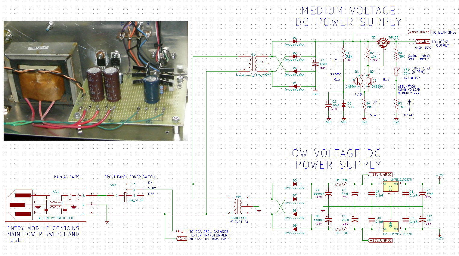
Low and medium voltage DC power supply These two power supplies provide the four primary operating DC voltages of the unit. These are, +18V unregulated for the high voltage board plus and minus 12 volts for the remaining circuits. The rectifier diodes in both low voltage supplies are BYV-27-200s. These are extremely fast switching rectifier diodes and will make the supplies very efficient by turning off as fast as possible. These are not necessary. But, I have bag of them lying around from experiments on high frequency switching power supplies. They are readily available and not expensive from Digi-key. The medium voltage supply's voltage regulator provides the power for the horizontal scan circuit. The voltage regulator is a text book differential amp type to keep the circuit simple. The voltage is adjustable between 25V and 35V to adjust the width of the horizontal scan within the monoscope tube. Not shown, is the extended front panel voltage adjust allowing easy size adjustment when changing the tube. The unregulated output 45V was not implemented. [HOME] [ELECTRONICS PROJECTS] [THE CHIEF TOP] [NEXT PAGE] |