|
LabGuy's World: The Chief, Part 6 - Major System Improvements November 10, 2021 After the initial design and construction were completed, several design issues came to light. First, the bare metal chassis was very unattractive. Second, there was a very annoying moving geometric image distortion caused by stray magnetic fields making the picture slowly undulate as if it were viewed under water. Third, there was a nagging issue with the video equalization. The picture had an annoying undershoot and overshoot in the video signal on sharp black to white transitions in the lower frequency areas of the image. This was characterized by a bright white patch following, to the right of, larger dark areas. Last was intermittant black bars flashing across the image when I tried to increase the contrast. That started right after I had made great improvements in the frequency equalization. Each of these issues were addressed in turn and solutions were found. Read on. 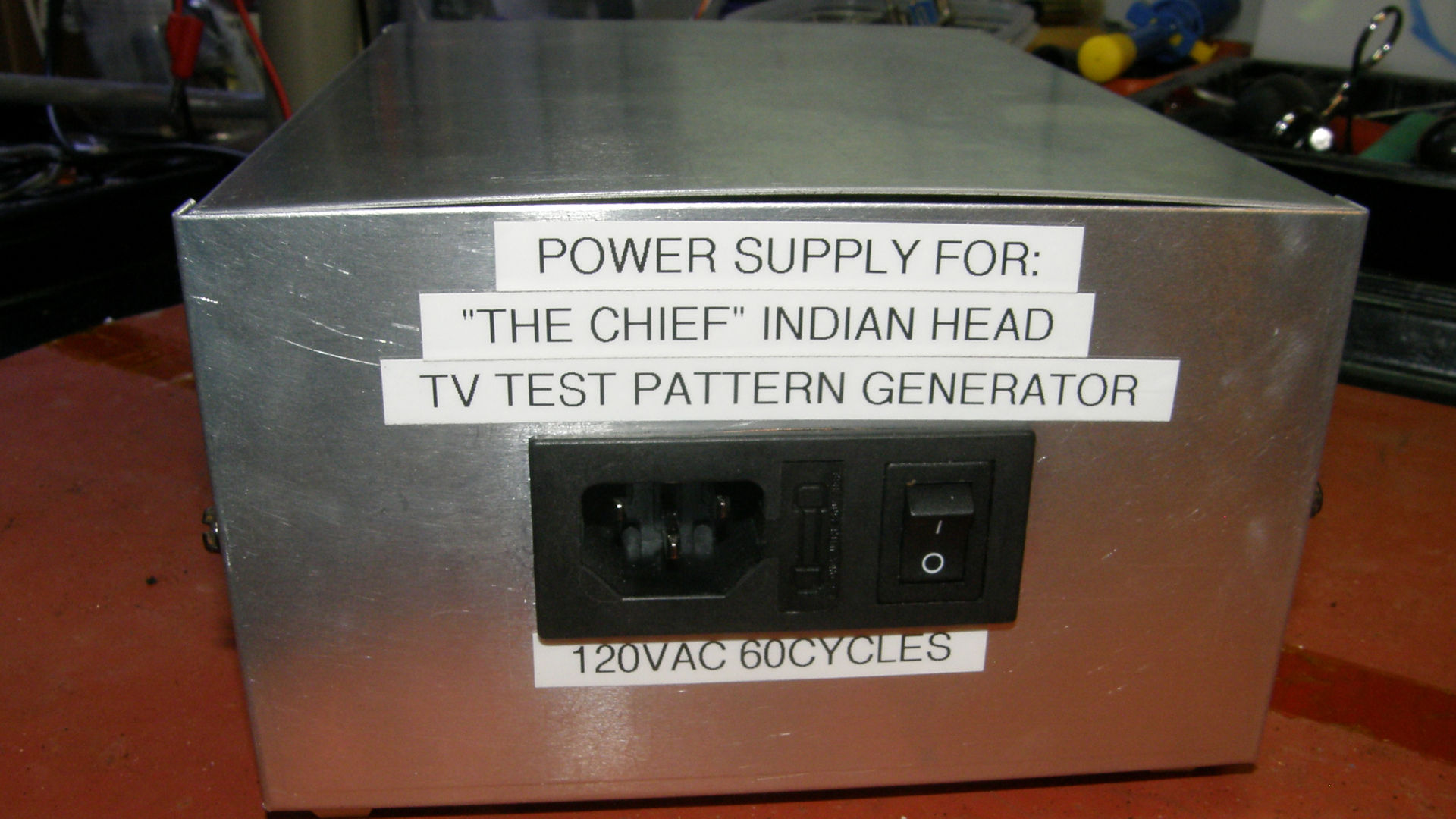
The New External Power Supply, front, rear views and schematic diagram The first major improvement I made to The Chief was to remove the power transformers from the main enclosure and move them to an external box that could be placed several feet away from the monoscope tube. The two chassis are now connected together by a six foot long multiconductor cable with large 15 pin Cinch/Jones connectors at each end. This moves the transformers far enough away from the main chassis to effectively remove the magnetic interfere with the monoscope tube. Steady as a rock now. 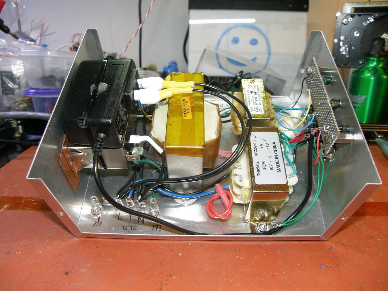
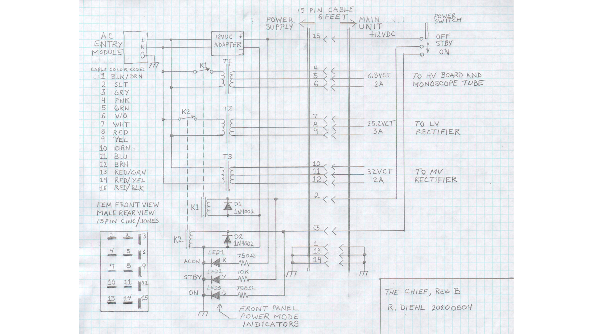
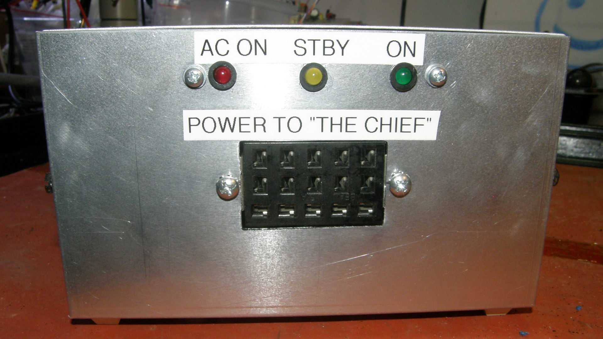
The new enclosure houses the three power transformers, the AC entry module, an additional DC power adapter that provides 12 volts DC to operate a couple of relays that select either the standby or the operate modes. This made it possible to control the box remotely from the main chassis with the original three position power switch. The operational mode is indicated by three LEDs on the power supply box. Primary AC power is controlled by the switch built into the AC entry module. When this switch is ON, the red "AC ON" LED is illuminated. When the main unit's power switch is placed into the STANDBY position, relay K1 is energized, the tube heater is activated and the yellow LED is illuminated. Finally, When the main unit's power switch is placed into the ON position, both relays K1 and K2 are energized, all internal electronics are powered up, the green LED is illuminated and The Chief's lithophane image is brightly lit. This upgrade was 100% successful. All magnetic interferrence has been eliminated. The live image looks like a still frame now. The picture is as steady as a rock. On to the next issue... 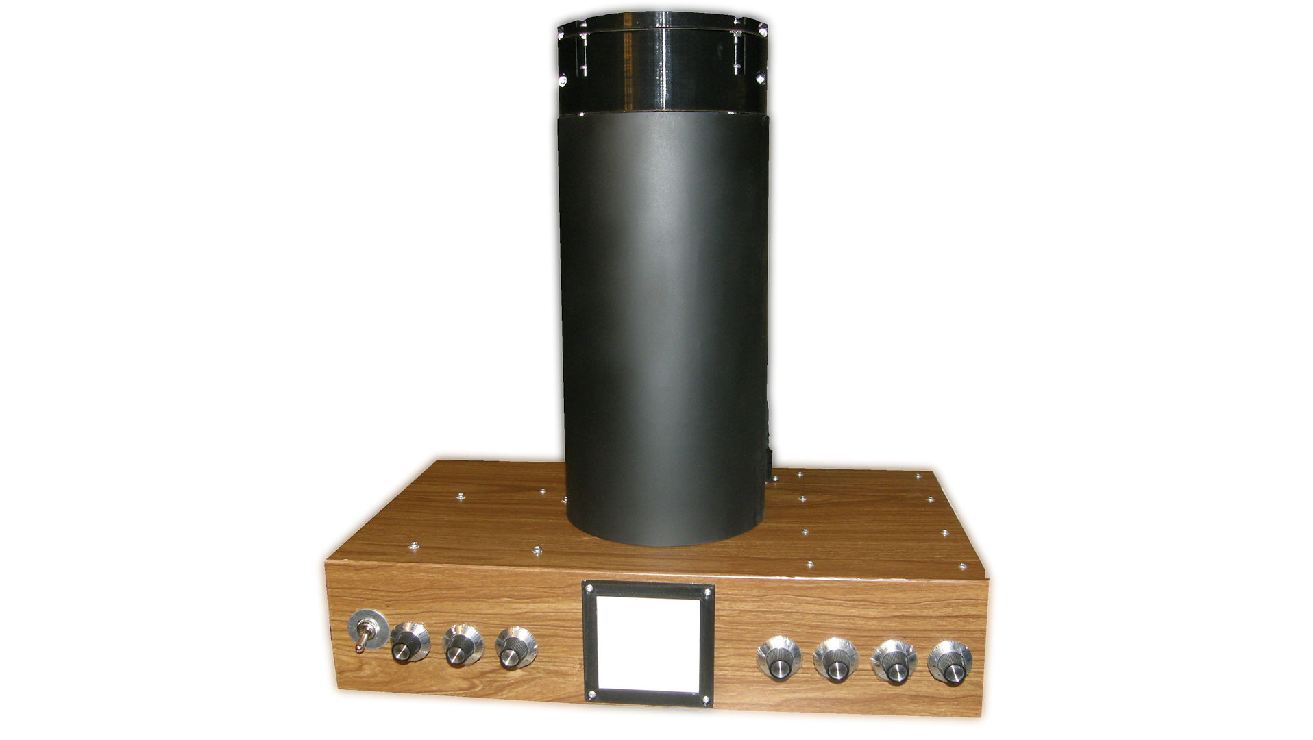
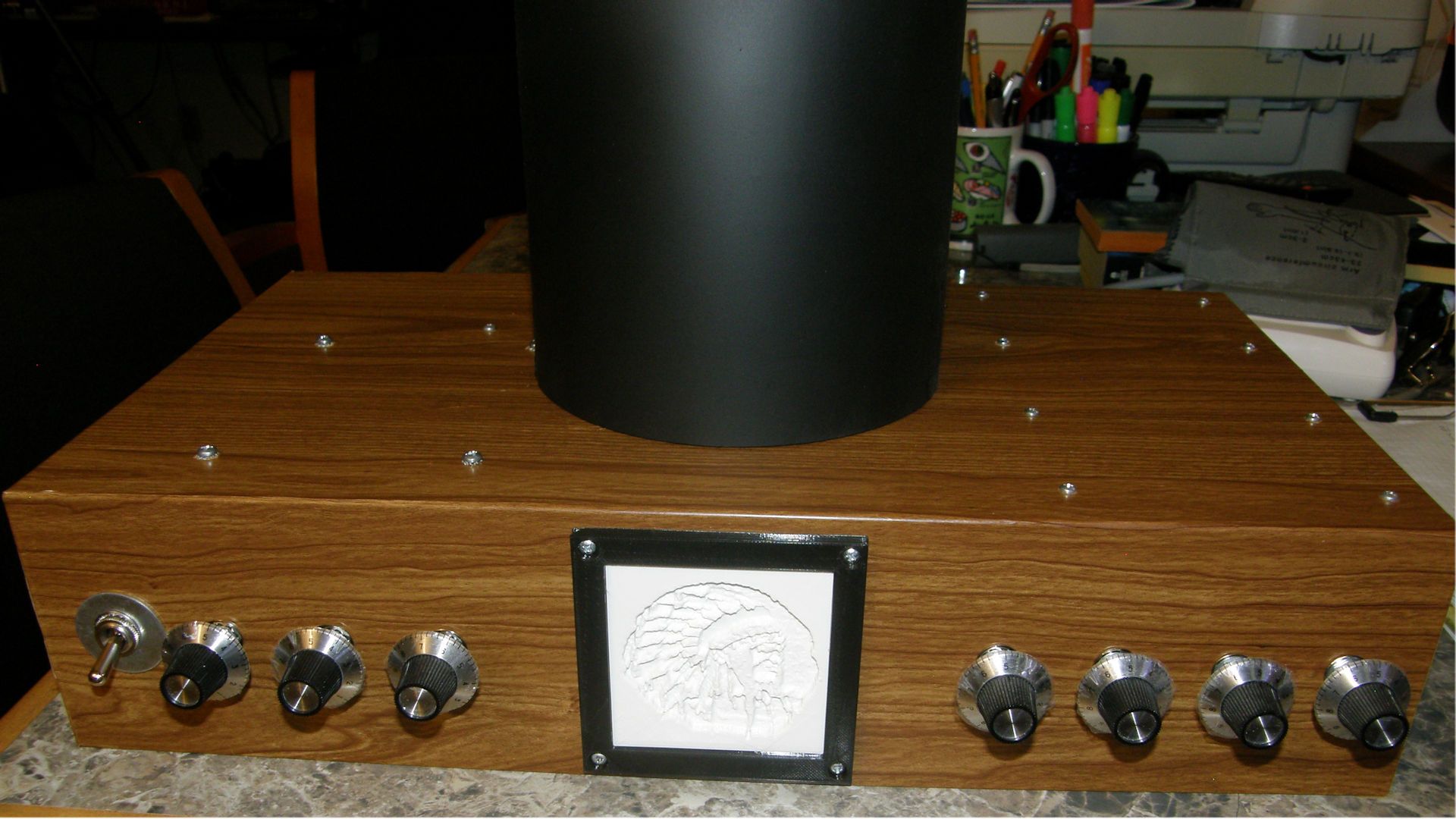
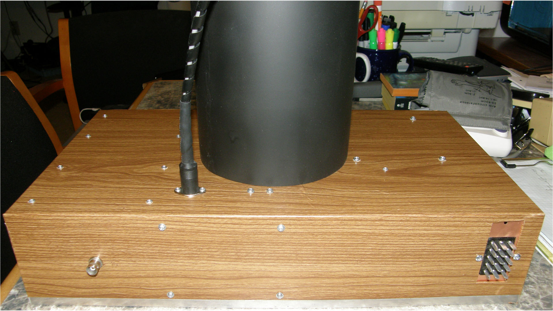
The Beautification Upgrade Some things are as simple as they are elegant. A covering of wood grain contact vinyl made the main chassis pop! It goes great with the seven matching black and chromium knobs plus the black framed lithophane pilot light. Sometimes, the best improvements aren't technical at all. The main chassis is now a thing of beauty. Visible, in the third photo, is the male Cinch/Jones 15 pin connector that receives the cable from the power box. 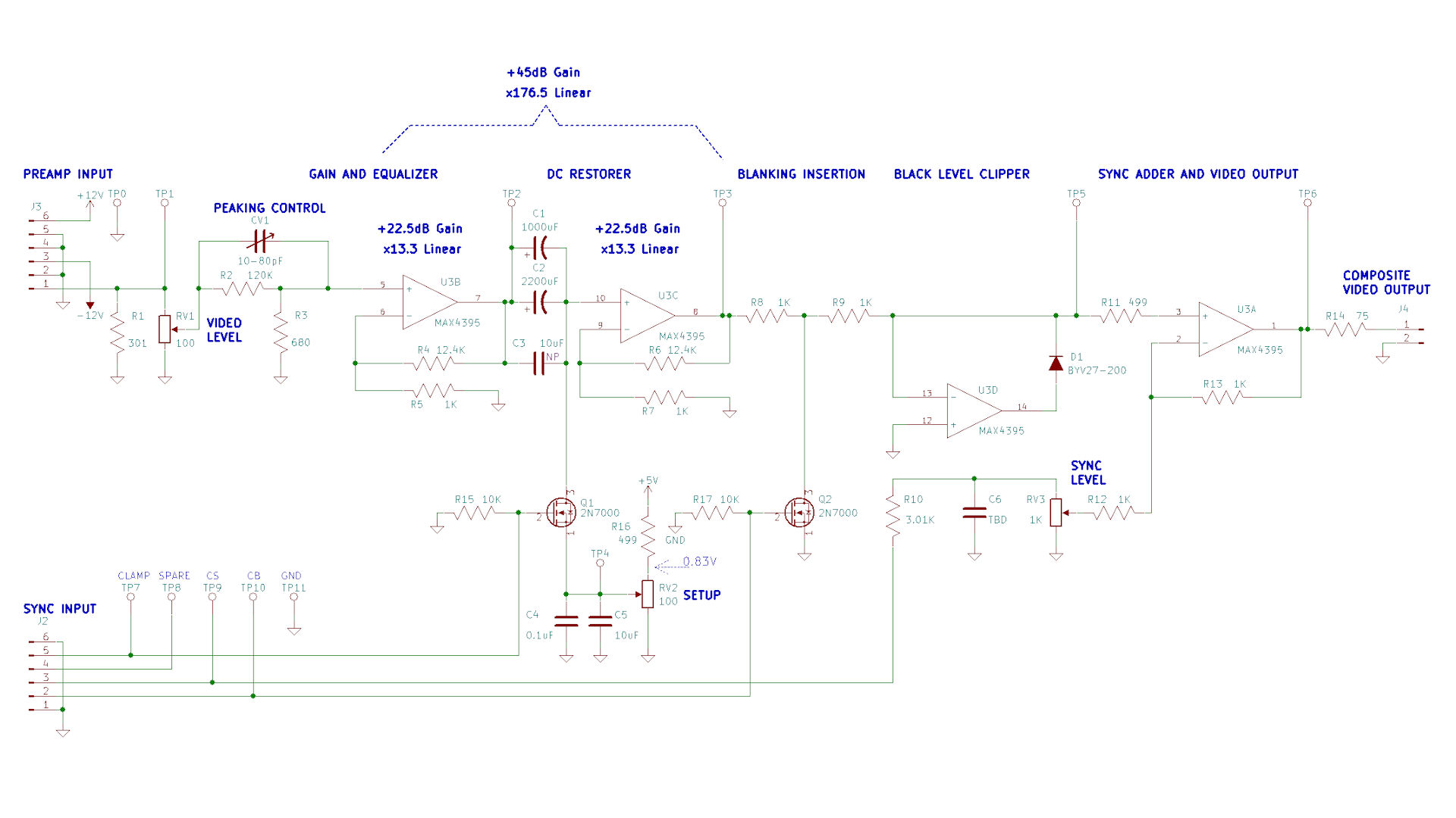
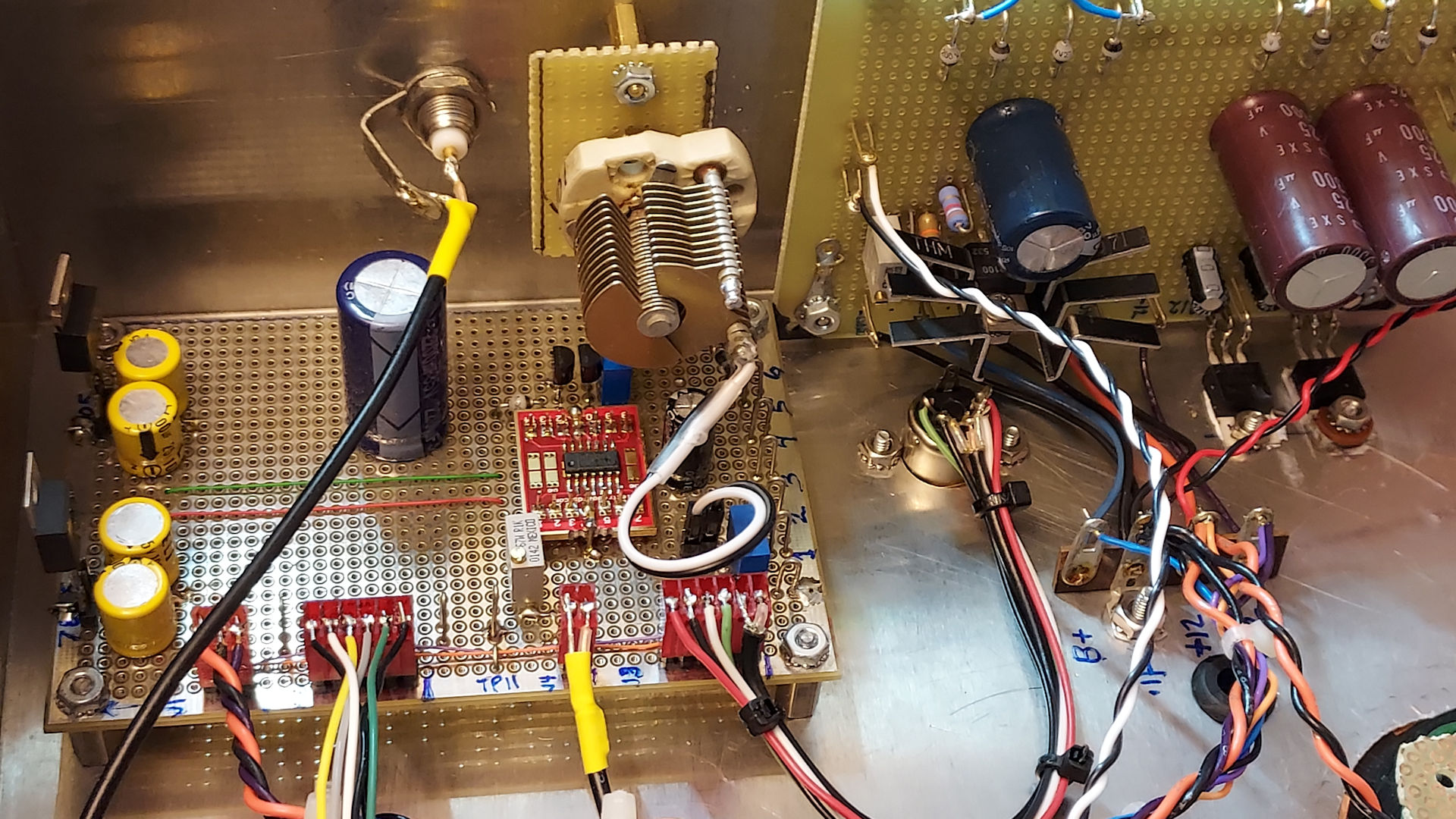
The final video processor schematic and the variable capacitor installed in the chassis It took me a while to come to understand that the overshoot distortion I was seeing in the video was due to parts tolerance issues. I had adjusted the frequency equalization with a variable capacitor and measured the exact value of that capacitor with my meter. Then installed the nearest fixed value capacitor in the circuit. It was not accurate enough. This introduced just enough distortion that could not be ignored. It took me some time to properly understand this problem and install the simplest solution. I put the variable capacitor back in the circuit and dialed it in to get perfect equalization. The capacitor was mounted on an insulating plate because it is not at ground potential. It could not be mounted directly to the metal chassis. It protrudes through the back side of the enclosure so that it can be tweaked as needed. NOTE: This is a temporary repair. The variable capacitor does correct the equalization. BUT, and its a big BUT, the darned thing is attached to a very high impedance node in the amplifier. The large area of the capacitor and its long leads are acting as an antenna. This has now brought switching noise into the video from the high voltage power supply. I have ordered some very small PCB mount variable capacitors which will not be succeptable to picking up this noise. Referring to the schematic diagram above. At the same time that the equalization problem was solved, a new problem arose. Of course. Annoying black bars started randomly flashing across the screen when the gain was increased above a certain threshold. This was caused by the first video opamp becoming unstable at very high gain. The gain had been added to make up for the loss introduced by the eaqualizing network. The opamps I used (MAX4395) are not optimized for very high gain applications. The equalizing network of R2, R3 and CV1 naturally drop the incoming signal by 176.5 times or minus 45 decibels. This loss must be made up by the amplifier U3B operating at a gain of 176.5 or +45dB. As mentioned, that is too much gain for one of these opamps. So, I divided the gain between U3B and U3C. U3C was originally operating at a gain of 1 as a voltage follower. Each opamp now operates at the quare root of 176.5 which is a gain of 13.3 each or only 22.5dB. The square root of 176.5 is 13.3 and 22.5dB is half of the original 45dB. The opamps are now stable at this lower gain and the flashing problem has been eliminated. Full image contrast can now be achieved without the black bars flashing across the screen. Phew! 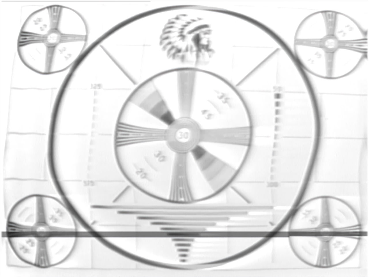
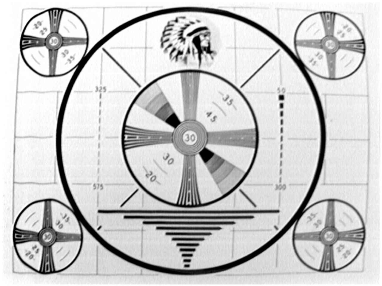
The Chief at his worst and his best. 20211111 The above images say it all. The frame grab on the left has low contrast, magnetic scan distortions, overshoot (seen to the right the horizontal black bars below the center circle) and the black flashing lines near the bottom of the frame. The image on the right has all of these problems repaired. Yes. There are other problems remaining. They are getting more and more subtle as progress is made. Rest assured that these will also be fixed as I get to them. Check back occasionally to follow the progress. That sums up the progress on The Chief.... for now. Thank you for taking time to read my article. [HOME] [ELECTRONICS PROJECTS] [THE CHIEF TOP] |