|
LabGuy's World: NBTV - Cathode Ray Televisor Project
[HOME] [ELECTRONICS PROJECTS] A Televisor with no moving parts? Is that even possible? Let's find out! 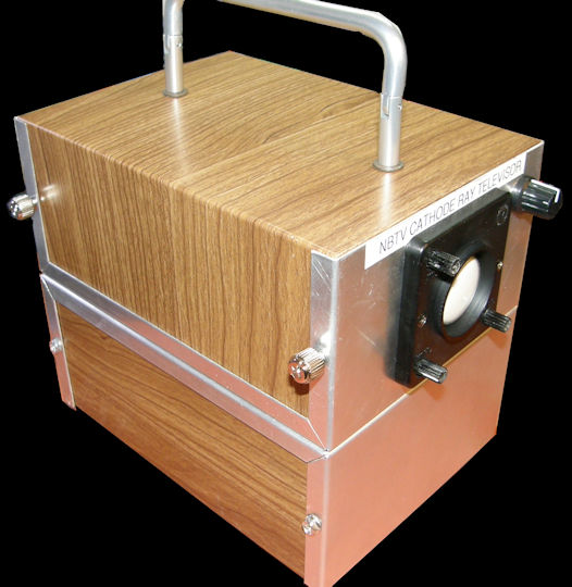
The NBTV - Cathode Ray Televisor Project Let's construct a 32 line NBTV (Narrow Band Television) televisor with a picture tube. To make it even more fun, let's use a tiny one inch picture tube. In fact, let's use a NOS (New Over Stock) James Millen 90901 miniature oscilloscope module, made in 1960, to make our task even easier. Yeah. That's the ticket! Let's get started then! Shall we? 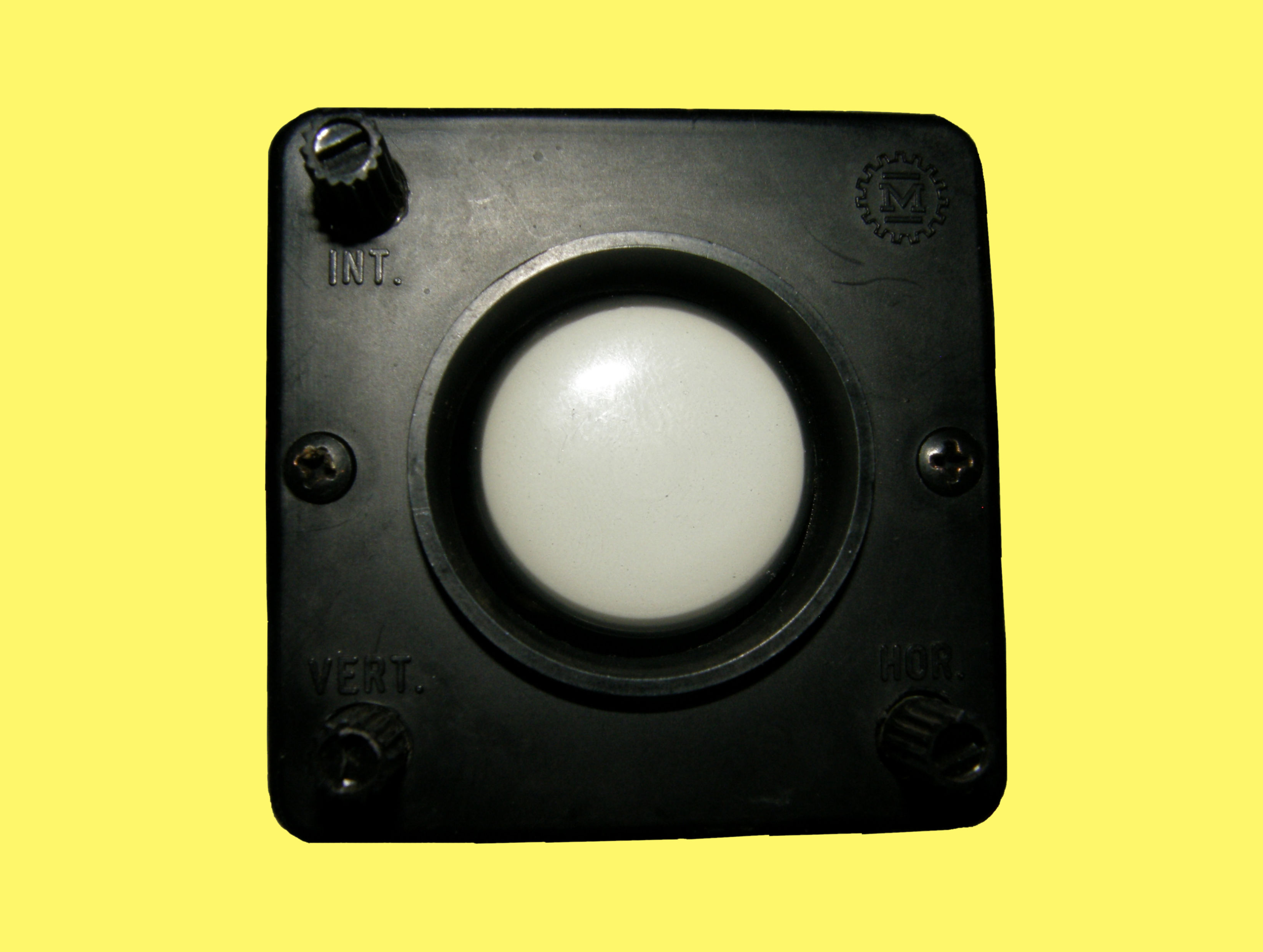
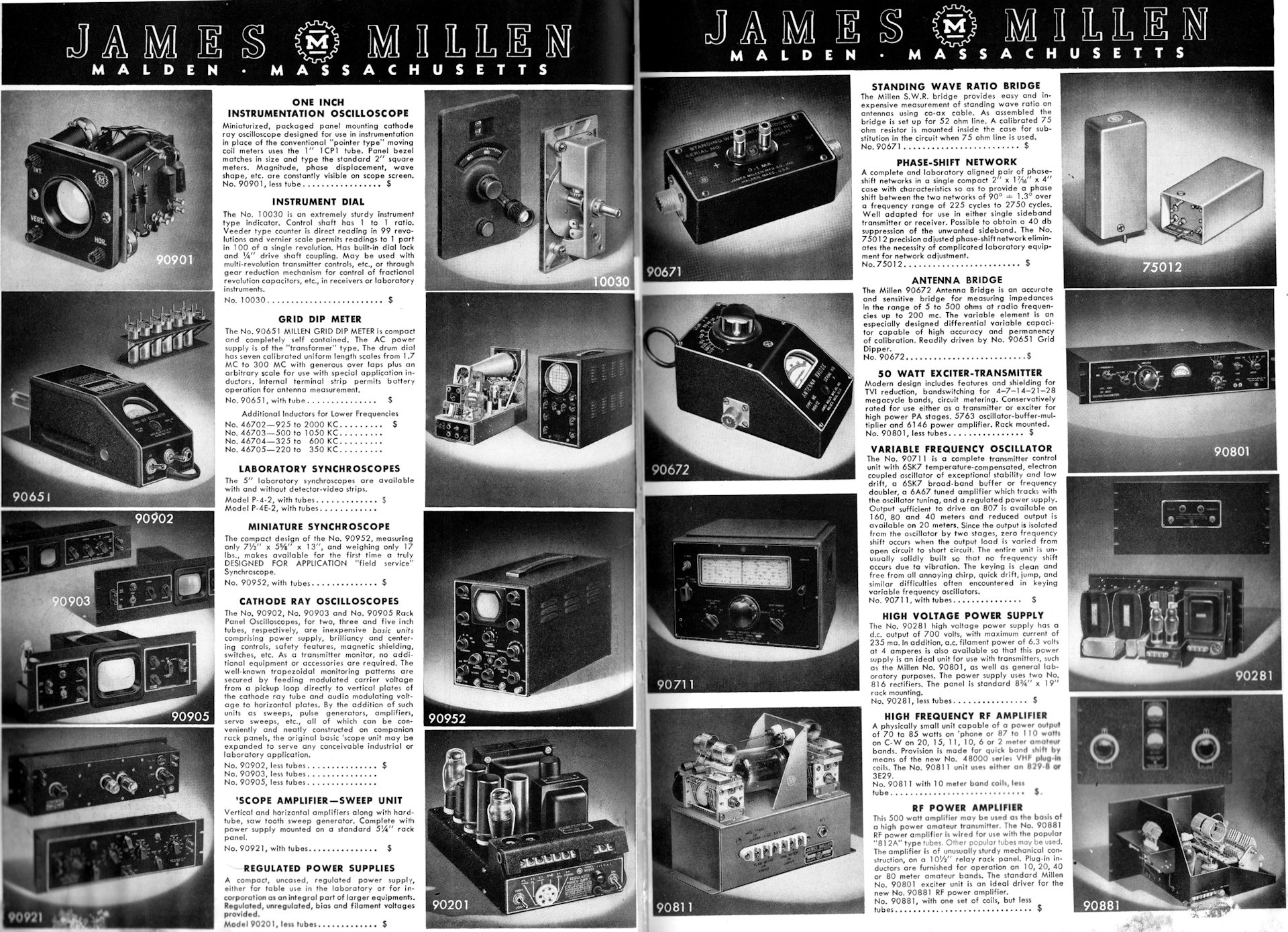
1950s James Millen Co. 90901 One Inch Oscilloscope Module. In 2020, this is a TRUE antique! Starting with the o'scope module's history, it was made in the 1950s for applications that would benefit from a simple oscilloscope monitor, but lacked the available space for even the usual compact models. I personally recall seeing the 90901 list price, in another magazine from the 1950s, for this oscilloscope at $34.95. The advertisement shown above is in the 1956 ARRL handbook, Advertising Index pages 24 - 32, found in the back of the book. I highly recommend that any reader of this page, find a copy of the 1956 ARRL handbook for your library. This is an AWESOME reference! 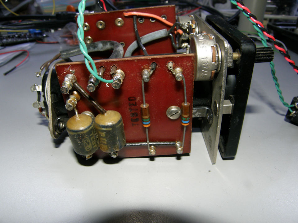
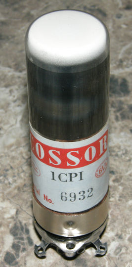
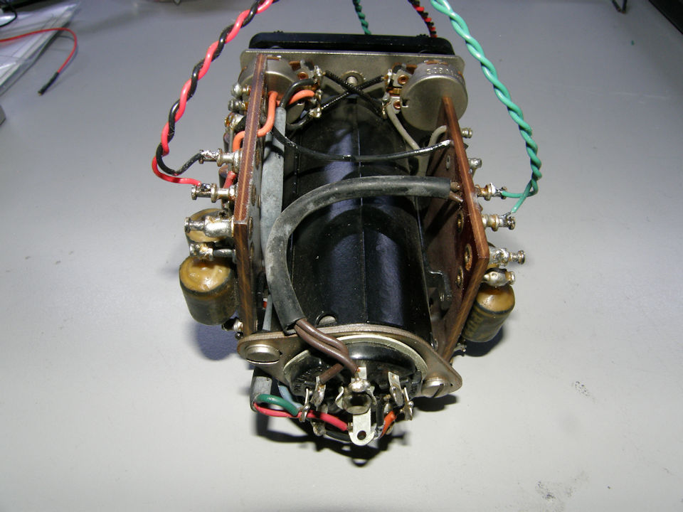
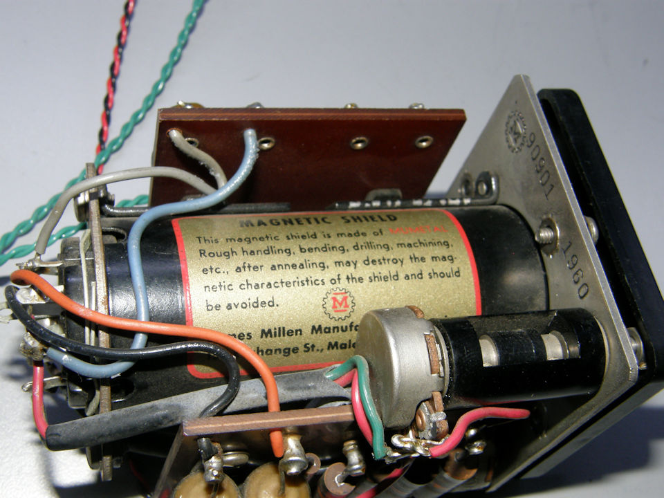
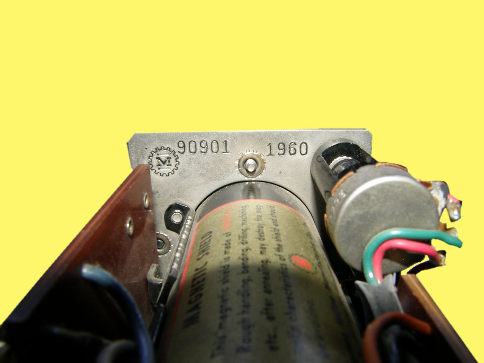
Some More Images James Millen Co. 90901 One Inch Oscilloscope Module in 2020. Ths unit uses the very small 1CP1 one inch electrostatic deflection cathode ray tube. This tube is no larger than a common radio tube of the day. It uses the innovative "Loctal" 8 pin base. This was an innovation for high vibration environments where common octal base tubes could be shaken loose from their sockets, like in automobile radios, for instance. The center pin is metal and has an indented ring at the tip. The socket has a wire grapple that grips the tube tightly. These tiny scopes found use in AM and single or double side band radio transmitters, frequency shift keyers (teletype and or telemetery) and built in panaoramic radio receiver spectrum displays. As mentioned in the advertising copy, it takes the form factor of a standard two inch square panel meter of the day. If it has not occured to you yet, you can copy this circuit very easily and even 3D print your own facsimile of the front panel bezel. Just saying... 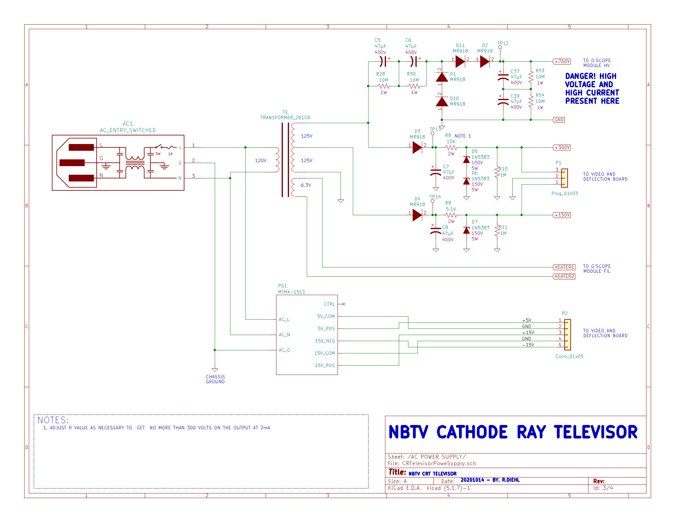
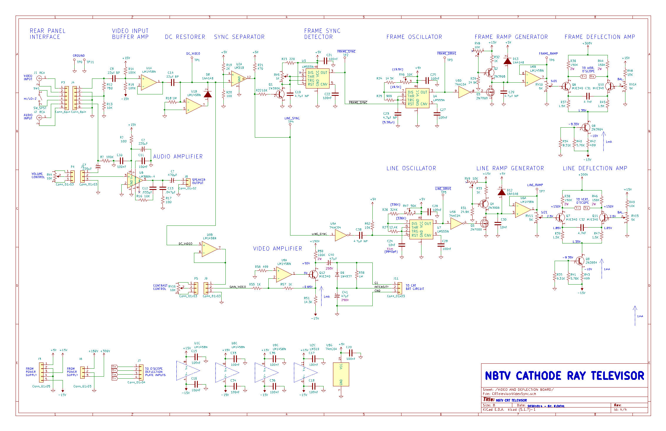
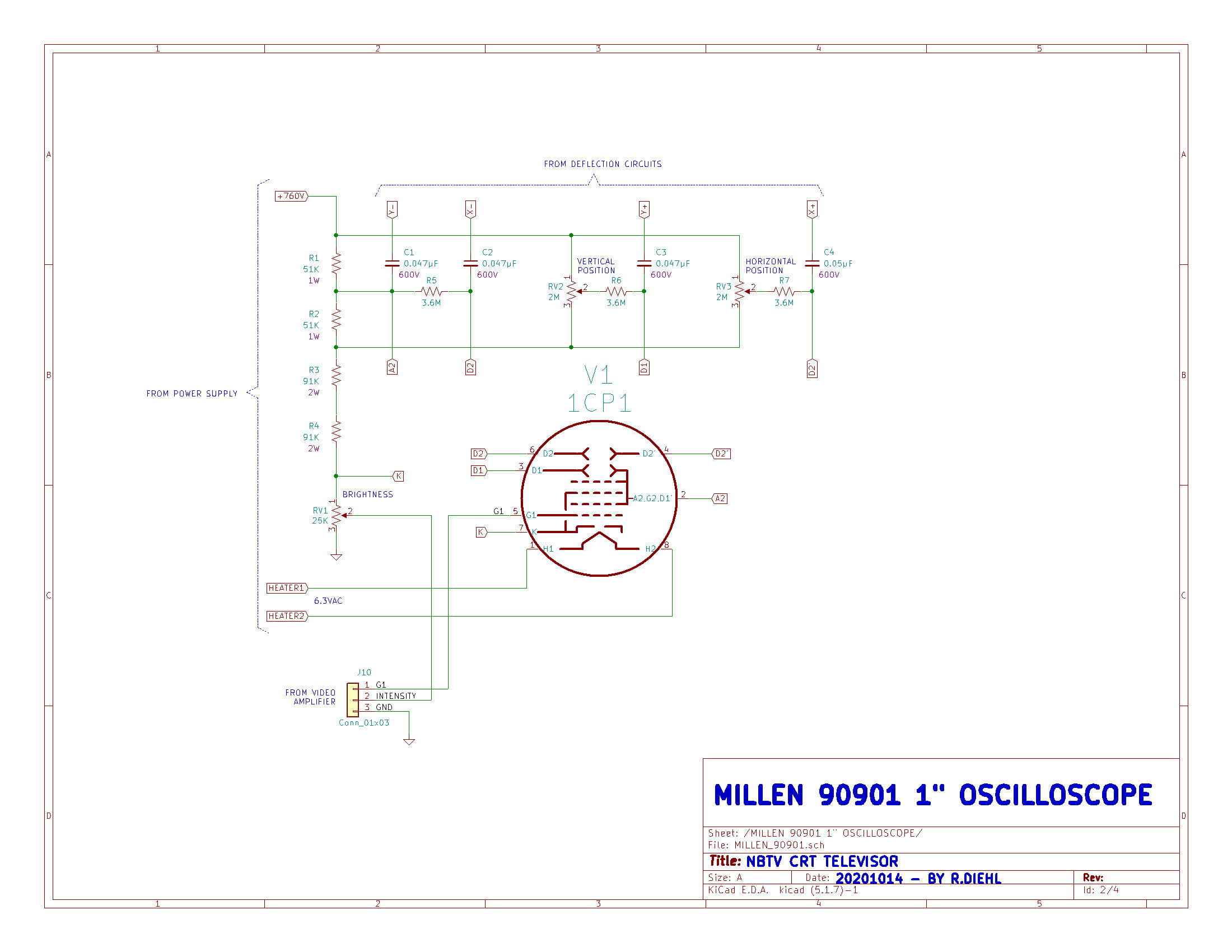
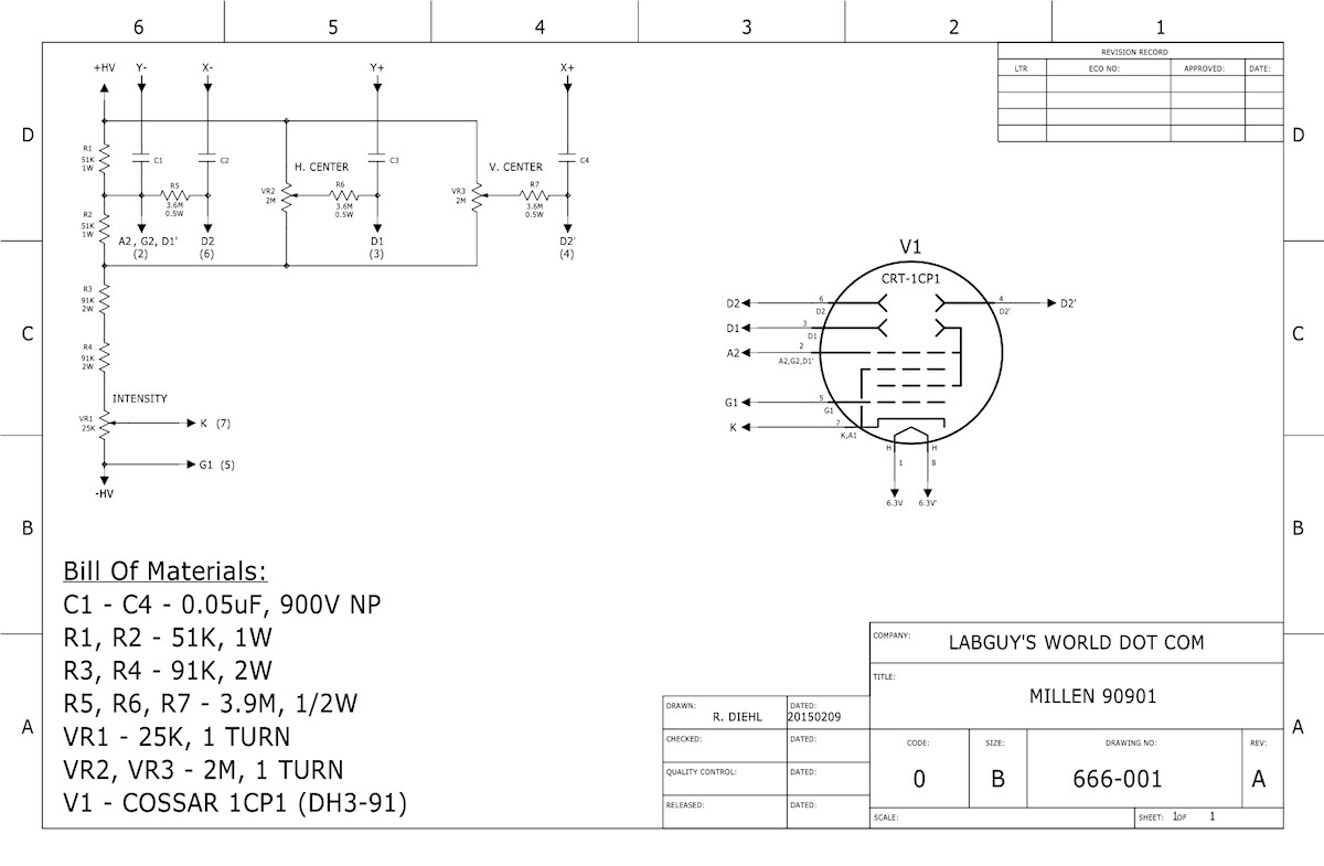
Schematics of the Cathode Ray Televisor Above are the schematics of the power supply, the video / deflection board and the modified Millen oscilloscope module. It couldn't get much simpler and still function. For a thorough deep dive into the circuit description of these electronics, see my YouTube video about that here: [NBTV Cathode Ray Televisor, Part 4]. This is a far easier method of absorbing the detailed information rather than you reading a ton of nerdly prose AND especially for me to have to write it all out! Besides, it's a pretty good video if I have to say so myself. If you are interested in obtaing the schematics in their original native Kicad version 5.1.7 format source files, please send me an email requesting them. Please note that these schematics are not in a form for making printed circuit boards, but just of the "whole system" in it's entirety. But, you are welcome to modify them all you want and as you see fit. 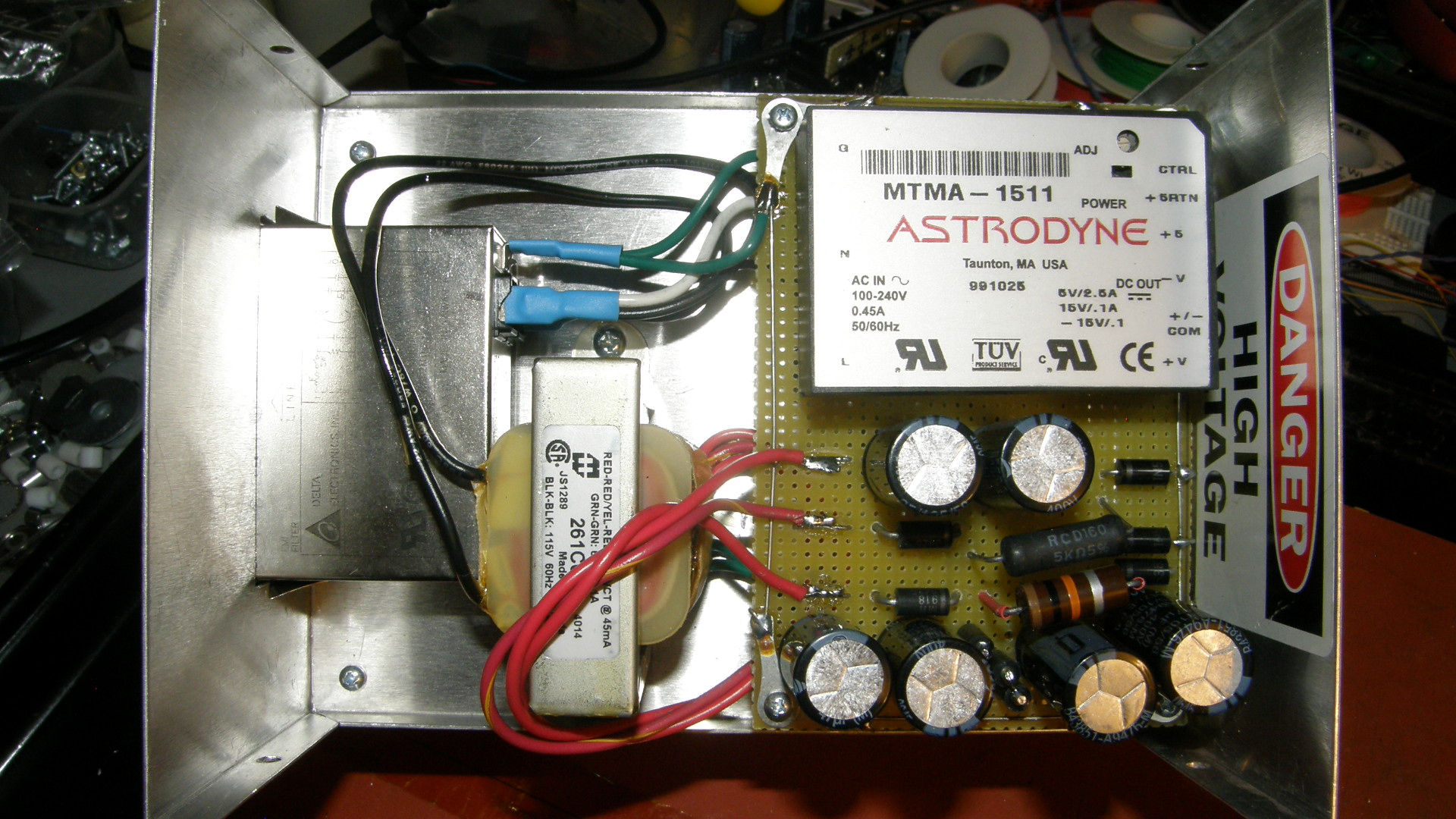
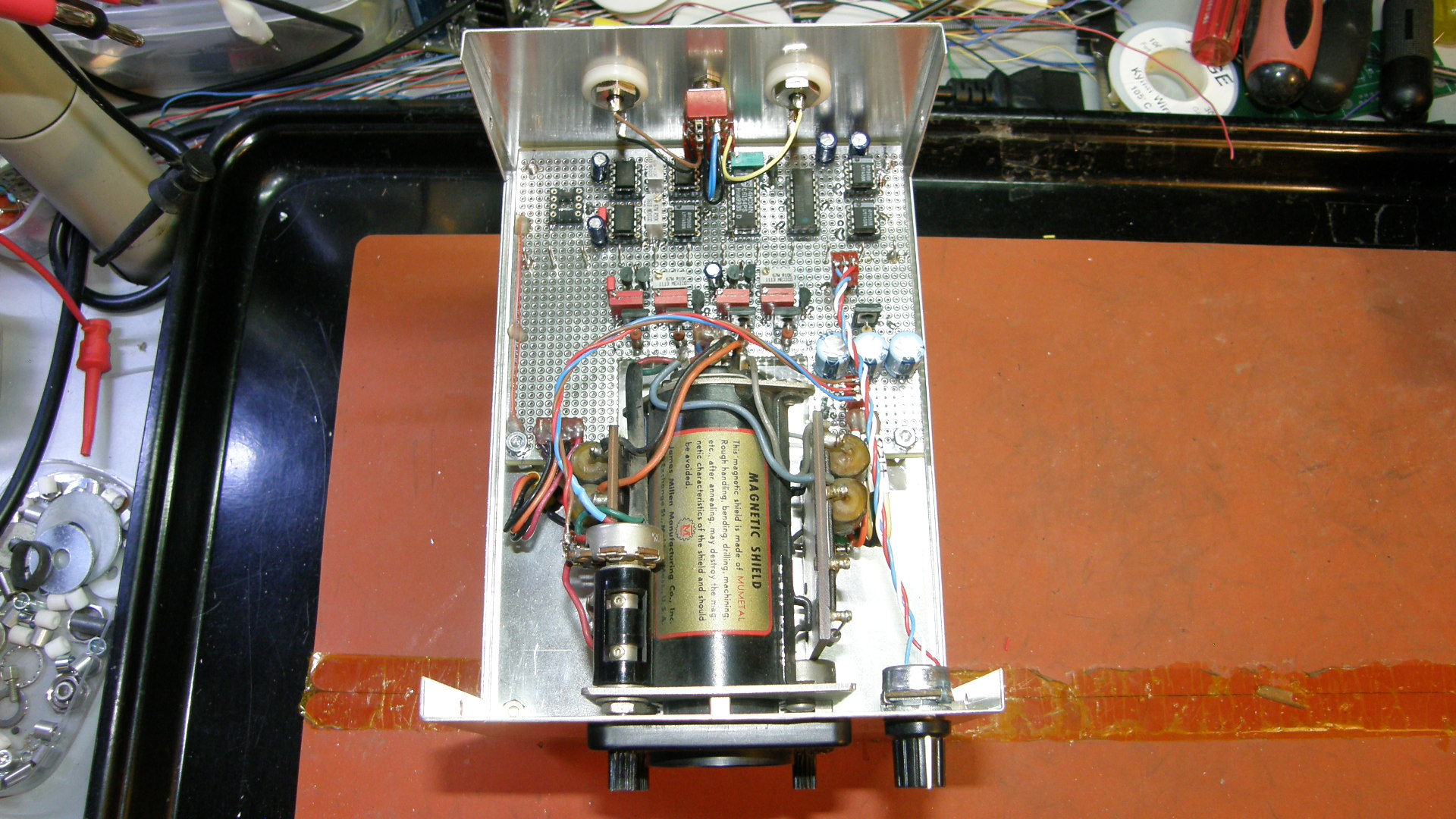
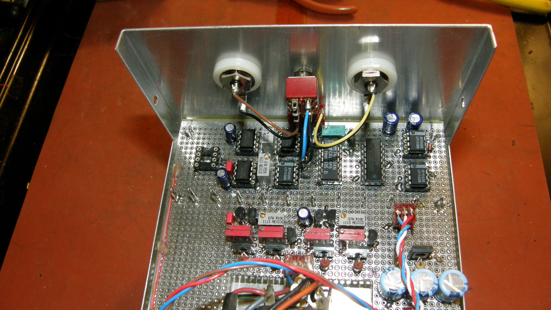
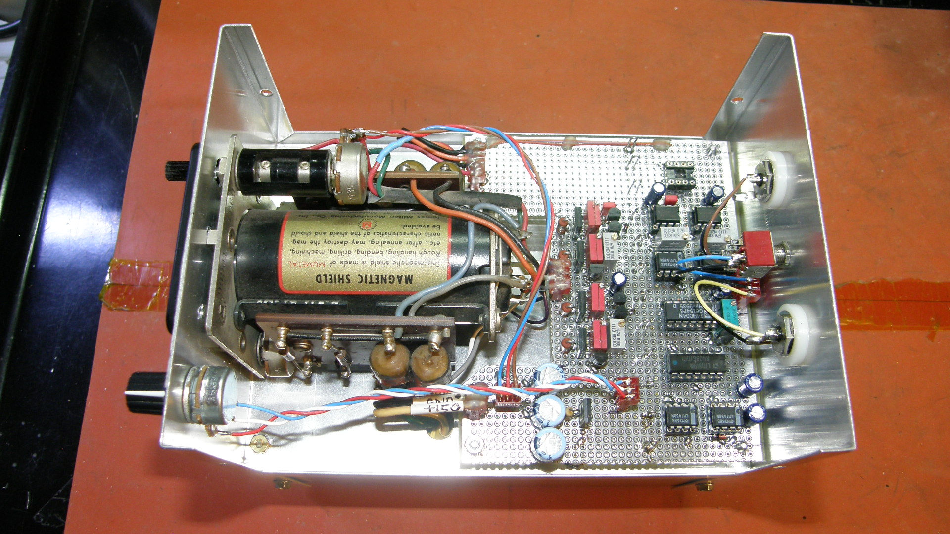
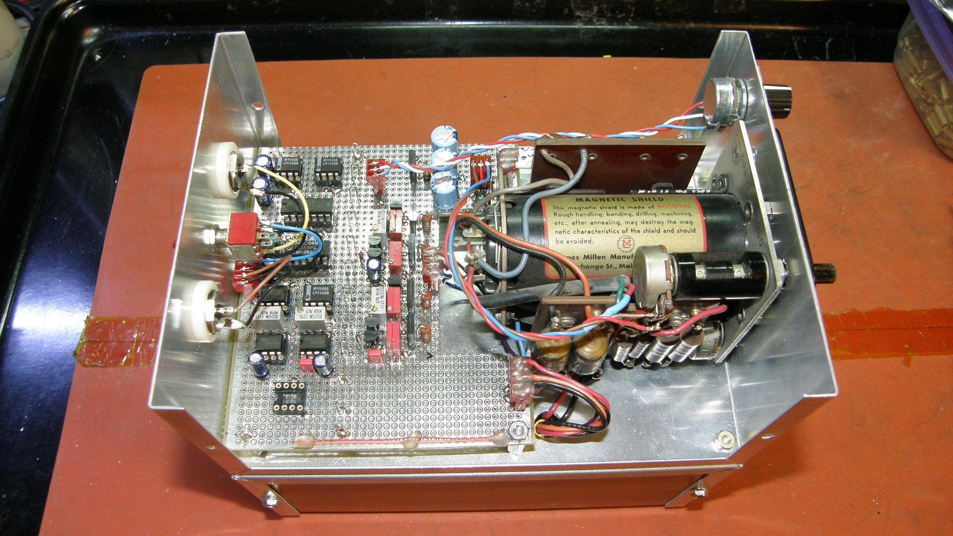
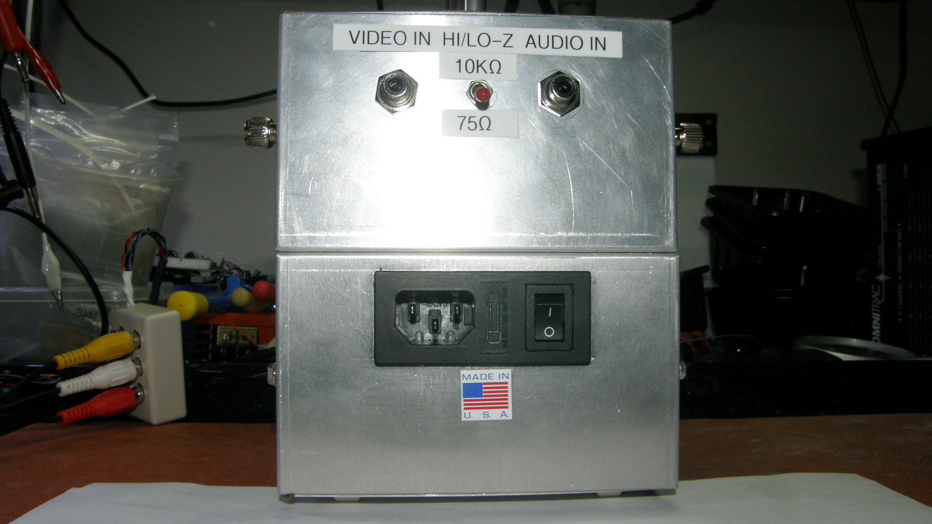
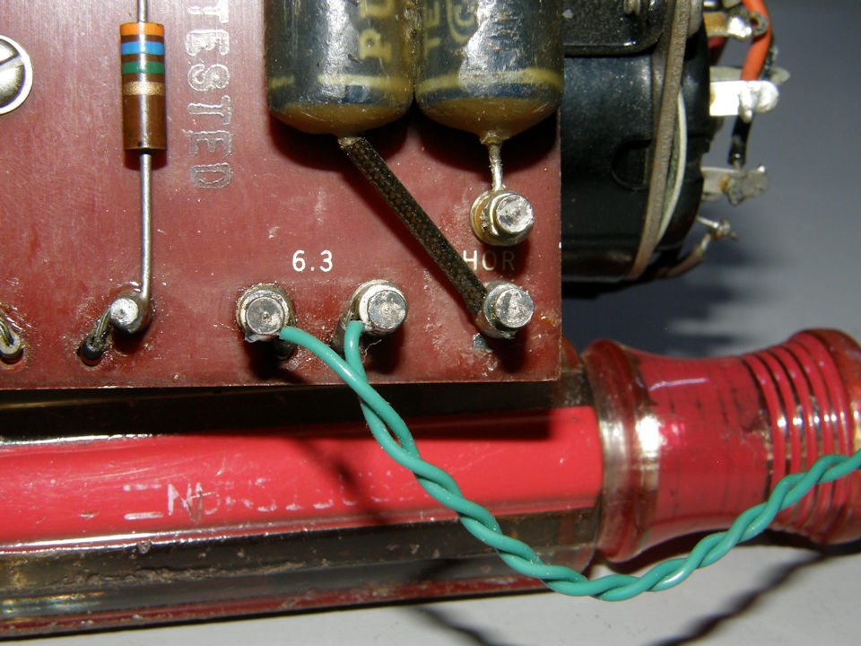
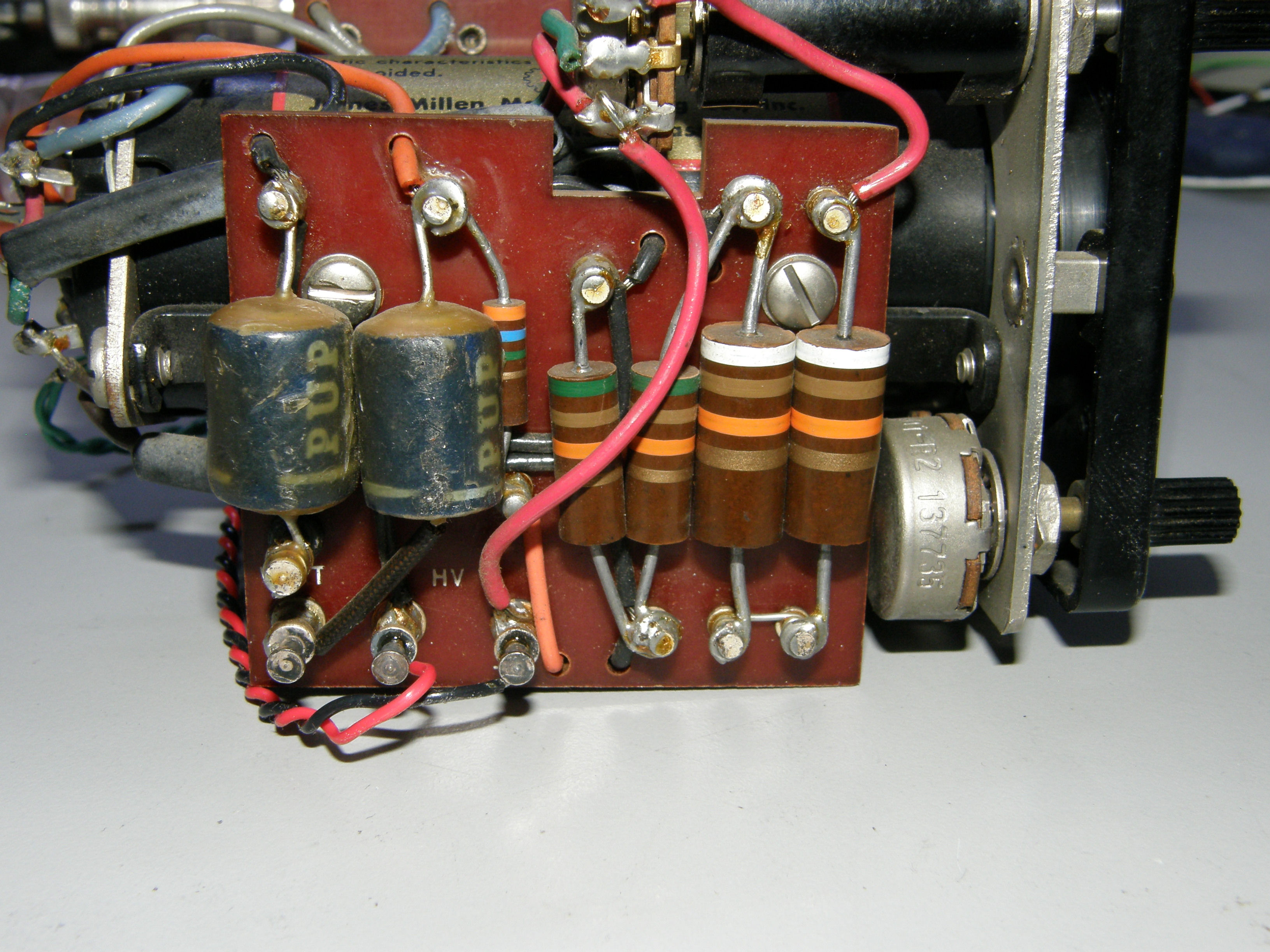
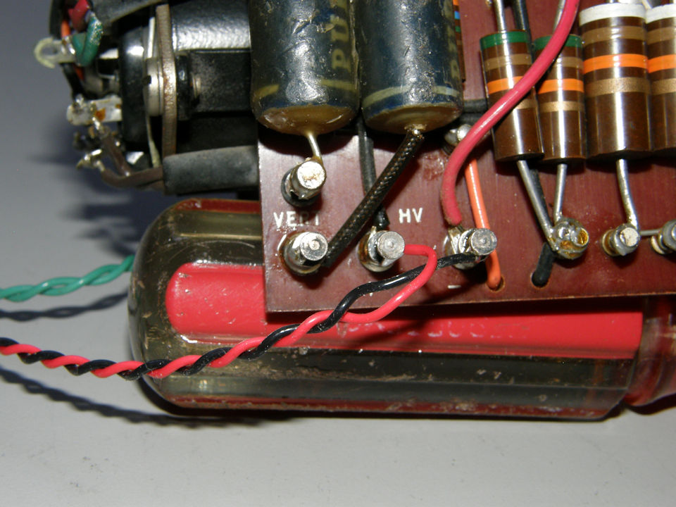
Interior Views of the Cathode Ray Televisor The cathode ray televisor contains two hand wired circuit boards, the oscilloscope module, a small iron core transformer and a small switching power supply. All housed in two small aluminum project boxes that have been bolted back to back to form two seaparate compartments. This isolates the power supply from the CRT section and (hopefully) cuts down on any magnetic interferrence reaching the CRT. This apparently worked, as there is no evidence of interferrence in the CRT or video signals. In the power supply section, the iron core transformer provides the 6.3VAC, 1 amp, filament power to the 1CP1 CRT. The 250V center tapped secondary winding drives the three separate high voltage rectifiers. There is a voltage doubler circuit providing 720VDC for the CRT circuits and two have wave rectifier sections providing +300VDC and +150VDC for the deflection circuits and the video amplifier respectively. These last two supplies are shunt regulated with zener diodes and appropriately rated current limiting resistors. The 300V deflection circuit supply is loaded with a constant 2ma and the 150 volt supply is also loaded to an average of less than 2mA. The iron core transformer, and the switching power supply, are powered by 120VAC that is filtered, switched and fused by a compact AC input module. The switching power supply, an Astrodyne MTMA-1511 medical grade unit, provides the +5V, +15V and the -15V for the low voltage components of the televisor. Video, audio and AC power enter the televisor through the rear panel. Video and audio inputs are via female panel mount RCA jacks. There is a switch to select either 75Ω or 10KΩ termination impedance. AC power enters through the AC entry module by way of a convenient standardized EIC power cord connect. The AC entry module also contains the primary ON/OFF switch, a common mode power line noise filter and a safety fuse. Easy peasy! The video and deflection circuits are constructed on ground plane vector prototyping board. All external connections are by way of convenient connectors so the board can be removed easily for servicing. The video and deflection board contains the following circuits: Input connectors and selectable video termination, input buffer amplifier, DC restoration, sync separation, frame pulse detection, frame deflection, line deflection, video amplifier and audio amplifier. All constructed very compactly by a liberal use of surface mount passive components on the bottom side of the board. This eliminated quite a few capacitors and resistors that usually would have occupied precious space on top of the circuit board. Front panel controls consist of the three original oscilloscope controls, Brightness, Vertical Position, Horizontal Position, as well as a separately installed Contrast Control. The audio circuits are not yet installed. There will be an eventually audio volume control placed to the left side of the panel in visually symetrical balance with Contrast Control. Of course, a speaker will be installed as well as soon as I dertermine how to cut the tiny oval shaped hole for mounting it or "them". I have two of these tiny 1" x 3/4" lap top speakers I plan to use. I am taking my time with them to avoid destroying the beauty of the currently constructed unit! 
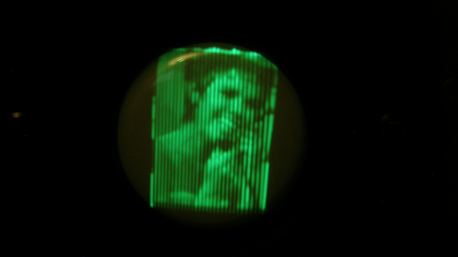
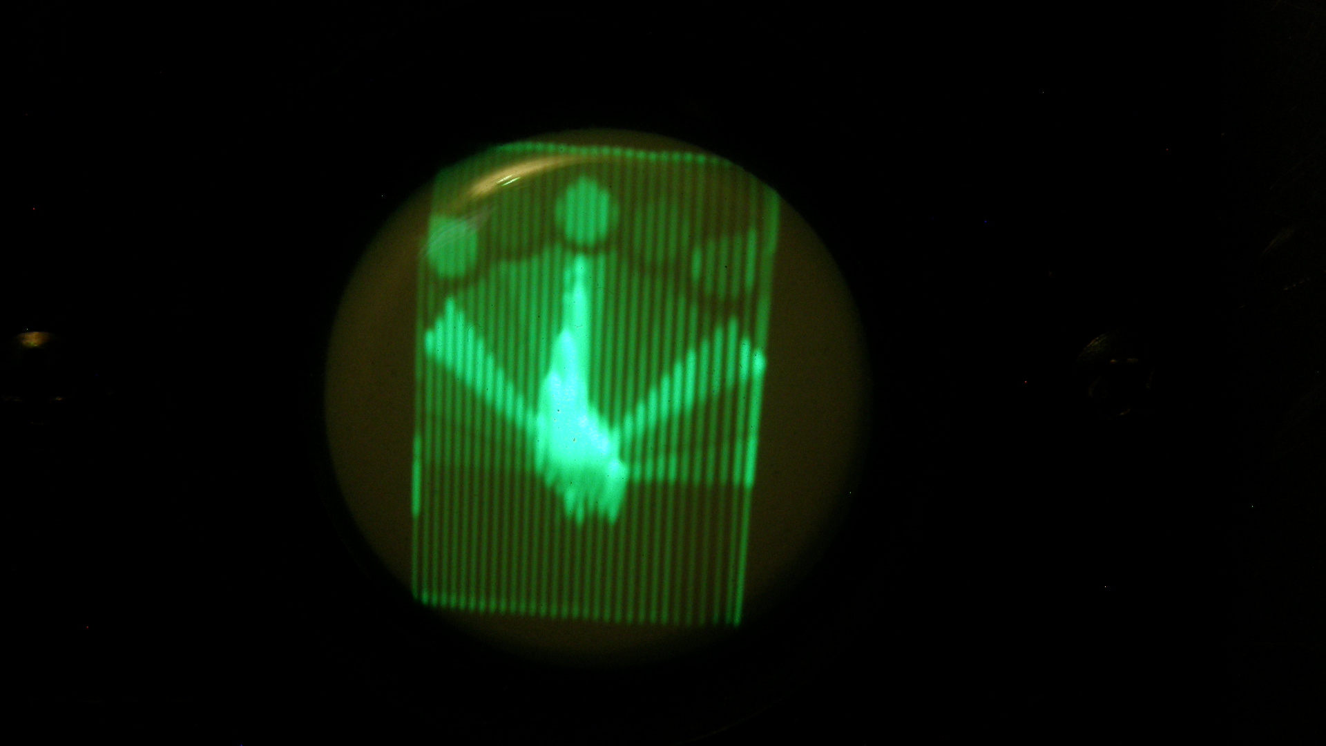
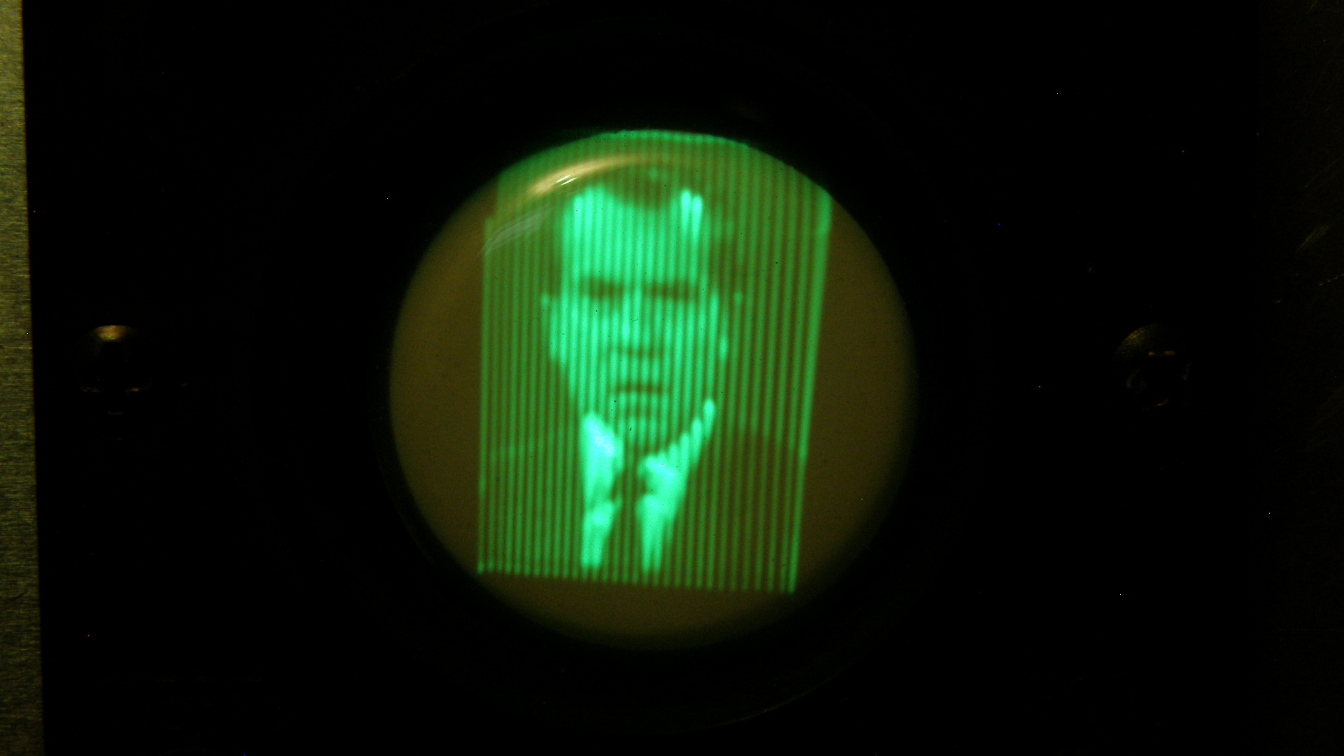
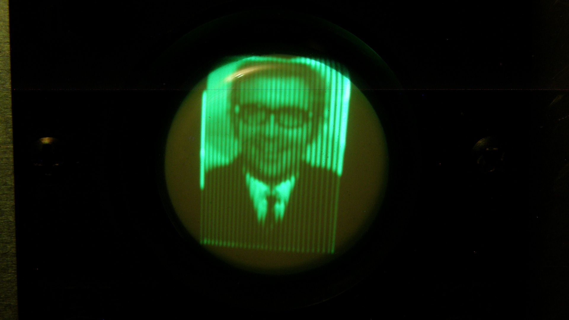
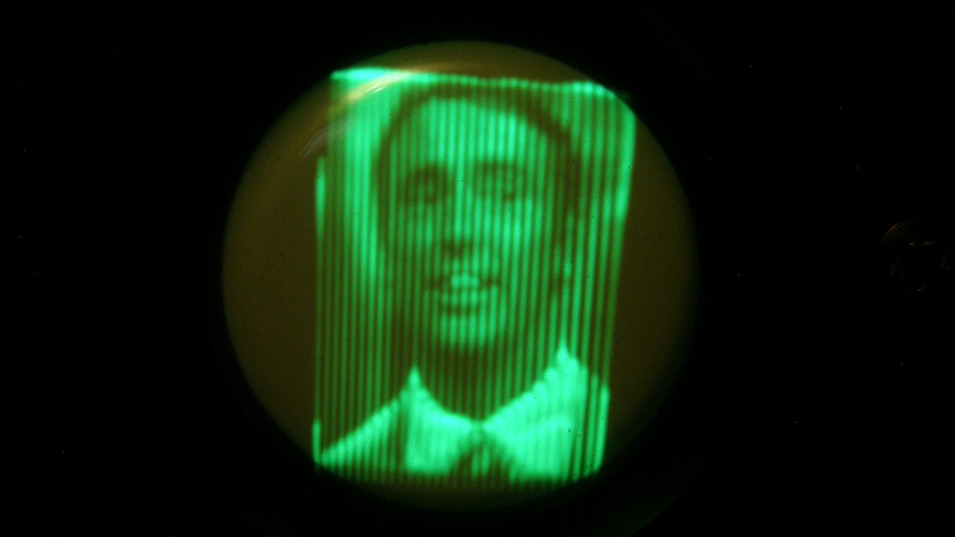
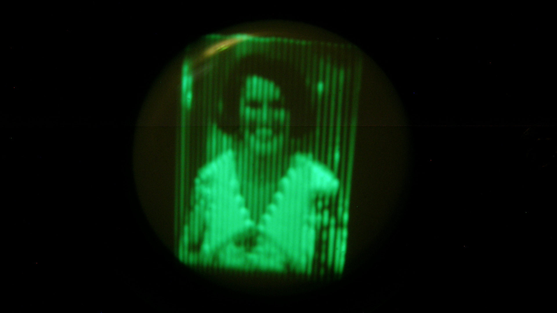
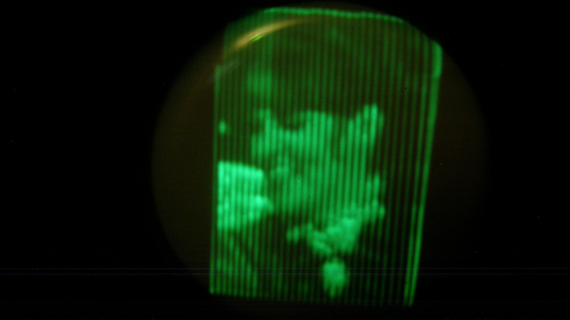
Off Screen Images from the Cathode Ray Televisor As can be seen in the photos above, the image quality can be nearly excellent - all things considered. You are not seeing things. The CRT is not rotated correctly in the holder and I have yet to go in and figure out how to correct it. But, I will. Be patient. Clearly, if you are watching these pictures live on the screen, the flicker at 12.5 frames per second is very noticable and somewhat annoying. It is also very difficult to record the moving images with video cameras that run at 24, 25 or 30 frames per second. That makes the flicker and other visual artifacts even worse. But, considering the simplicity of the system and the era in which it was developed, the results are astounding to say the least. 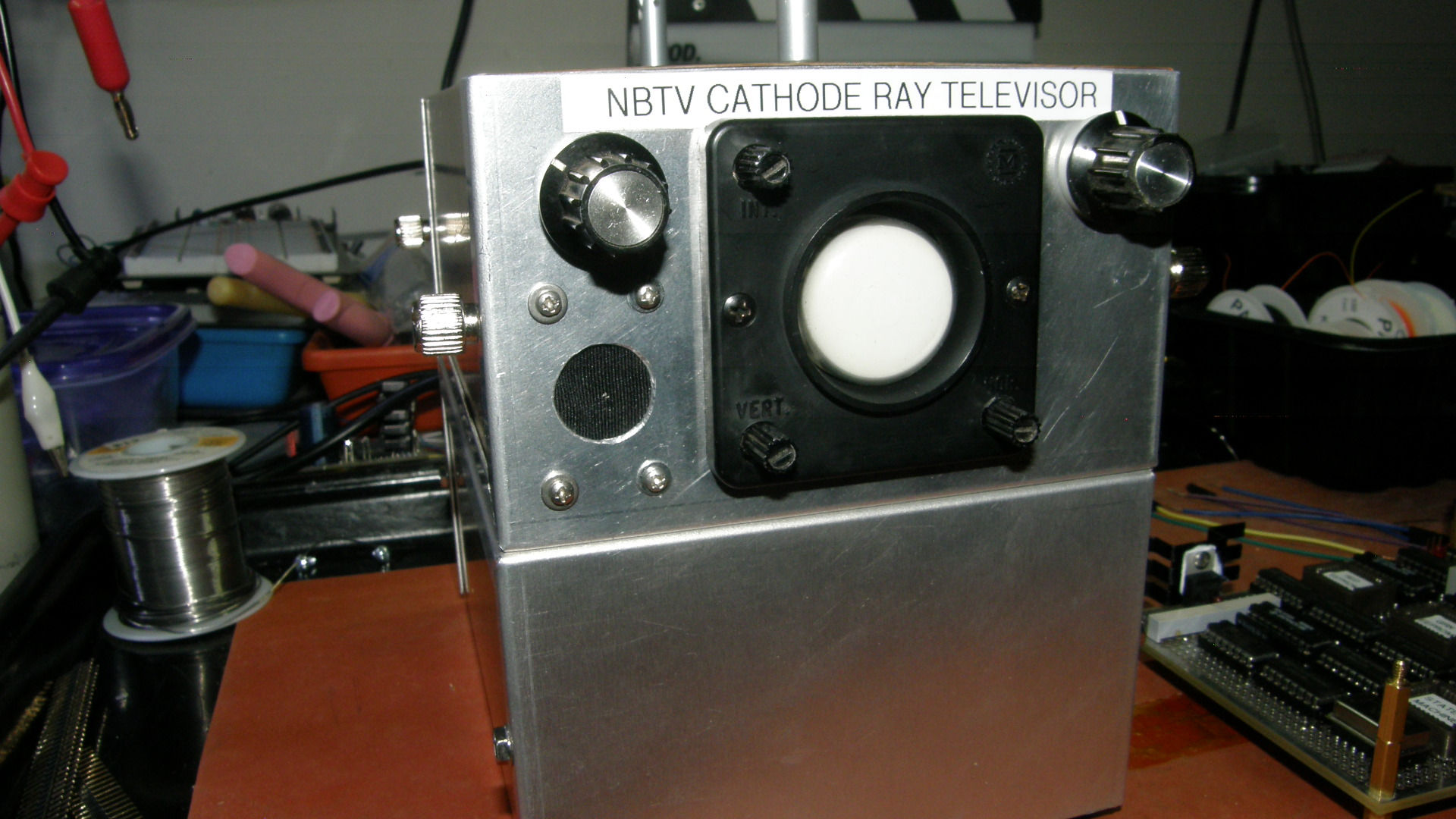
Cathode Ray Televisor with a new loud speaker! What good is a TV without sound? I had included the audio amplifier from the get go. Refer to the audio circuit in the schematics shown earlier in this article. I had even ordered the cutest itsy bitsy speaker you ever did see. It took a while, but I finally got around to installing the darned thing. As you can see in the photo above, the potential for destroying the good looks of the otherwise completed project were greater than zero. In the end, it did not come out too shabby. It even sounds pretty good, all things considered. 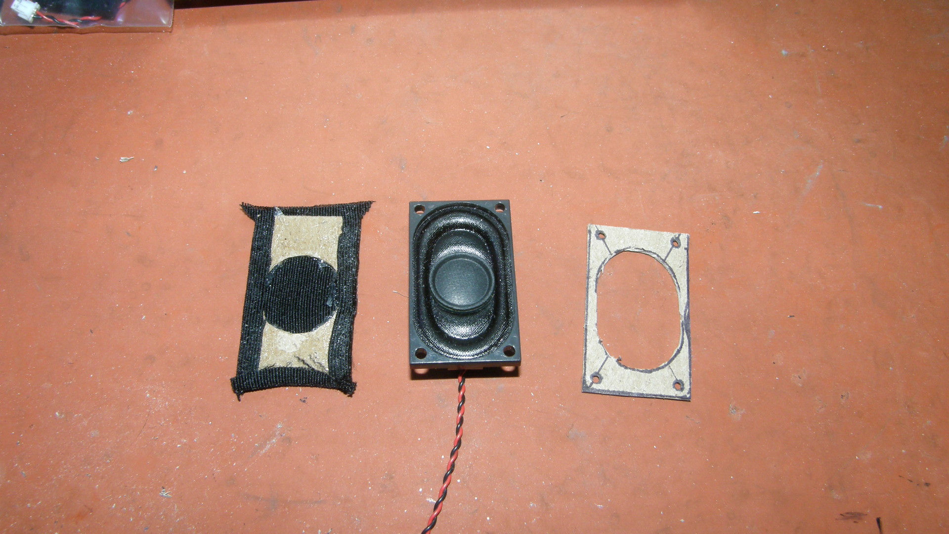
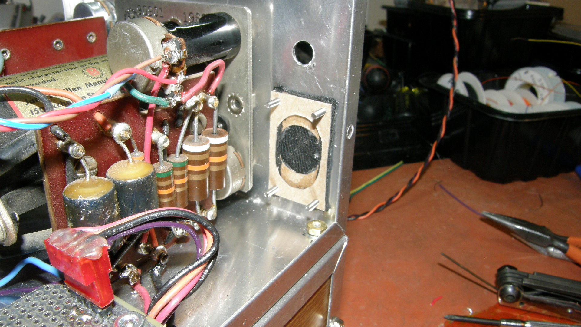
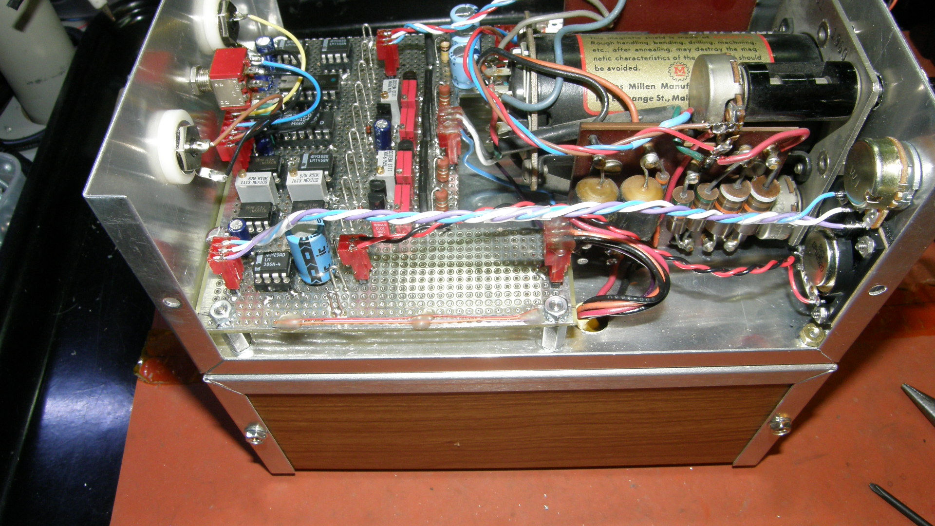
Cathode Ray Televisor loud speaker installation. Starting out with the tiny 8 ohm speaker, I made a cloth covered grill for it. The front view of the grill was so poor after I made it, I decided to mount it inside the case. Originally intended for the outside, to visually match the bezel of the CRT. It failed miserably. The glue had bled through the cloth and the cloth did not stretch evenly over the tiny panel. Face it. The thing was butt ugly. You can get a small sense of that from the back side view of the speaker grill cloth in the first photo. So we went with the second option as you can see in the second photo. Using the cardboard remnent from the back of a writing tablet, I cut out the grill support and the speaker spacer with an Exacto knife with a brand new super sharp blade. It is all mounted in the case with #2 hardware. The volume control and speaker connect to the main board with Molex connectors like all the other off board circuits. This all came out as planned. The LM386N-4 audio amplifier chip can be seen at the far left of the last photo, right next to where the volume control plugs into the board. No project is complete without an unanticipated problem and this one is no exception. The magnetic field from the speaker can cause deflection distortion on the CRT if the volume is turned up too high. Oh, well. At moderate and still adequate sound levels, it sounds good and the picture is not disturbed in any visible way. I consider the Cathode Ray Televisor to now be a completed project. Check out the up coming 10-4 Eleanor, an NBTV Color and BW video signal generator. [NBTV Cathode Ray Televisor, Part 1] (47 minutes, 7 seconds) Construction begins. [NBTV Cathode Ray Televisor, Part 2] (7 minutes, 30 seconds) Construction progress report. [NBTV Cathode Ray Televisor, Part 3] (17 minutes, 1 second) Unit completion and operational demonstration with flickery video. [NBTV Cathode Ray Televisor, Part 4] (39 minutes, 30 seconds) Circuit theory deep dive with still frame screen shots and project photos. [Cossor 1CP1 Product brochure and datasheet] [HOME] [ELECTRONICS PROJECTS] |