LabGuy's World: The Chief, Part 4 - Deflection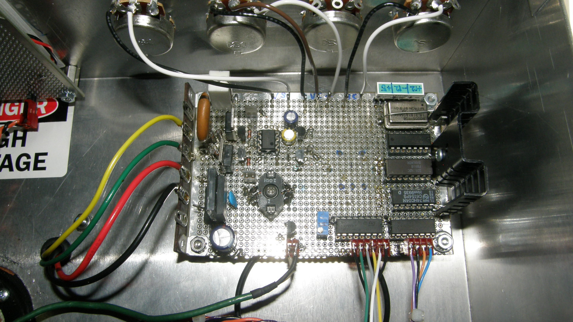
The entire sync generator and deflection board. The deflection board is very compact and contains everything for magnetically scanning the monoscope tube. Sync generator, horizontal scan, vertical scan and beam blanking circuits have plenty of elbow room on this board. The four off board potentiometers are, from left to right, vertical size, vertical centering, horizontal size (not yet implemented), and horizontal centering. On the left side are the deflection yoke connections. Yellow/green are the vertical coils and red/black are the horizontal coils. Connectors across the bottom, from left to right, are beam blanking output, video board bound sync pulses and power input. The large heat sink on the right side is for the LM7805, 5 volt regulator. 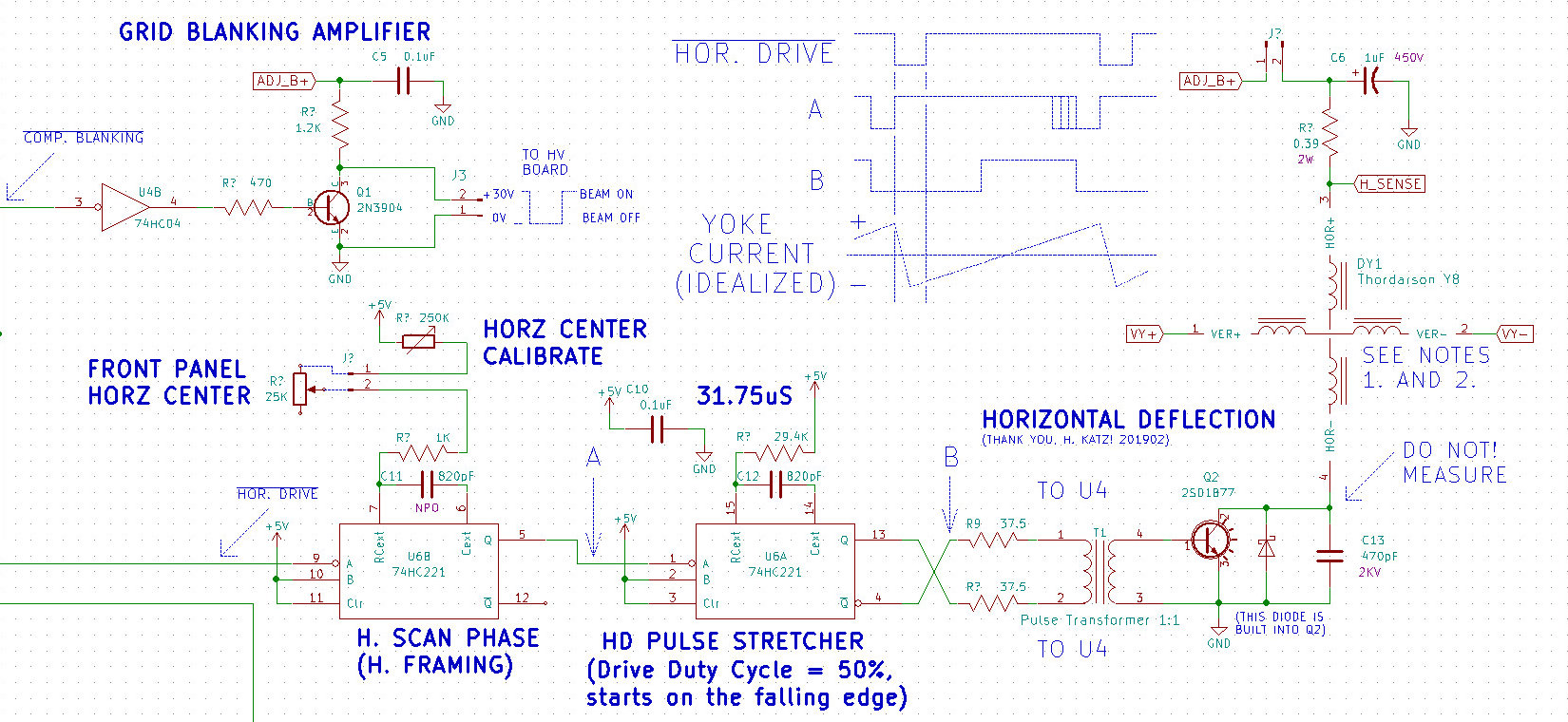
Beam Blanking and Horizontal Deflection Schematic Diagram First, in the upper left of the diagram, we see the beam blanking amplifier. It takes low going TTL level 5V pulses and amplifies them to 30V peak. This is sent to the high voltage board and AC coupled to G1 in the monoscope to blank the beam during retrace. The blanking amplifier gets its power from the same power supply that powers the horizontal scan. It couldn't be simpler. The horizontal scan output transistor direct drives the deflection coil in the yoke. When the transistor is on, C13 is shorted out and discharged while current flows through the yoke. At the end of the scan, right side of the screen, the transistor turns off and the magnetic field collapses abruptly and sends the beam rapidly back to the left side of the screen. During this phase, C13 is charging through the inductor AND forming a resonant circuit with it. The value of the cap is chosen such that the L and C form a resonant circuit tuned to the retrace time. The yoke then charges through the cap, until the midpoint of the scan where the output transistor once again switches on and the cycle repeats. Horizontal drive, from the sync generator is sent to the H. Scan Phase multivibrator, U6B, or timer, as I like to call them. This timer's job is to position the horizontal retrace inside the blanking period. The effect is to act as a picture centering control as well. This is a front panel adjustment. U6A, the second timer's job is to take the falling edge output of the first timer and create a horizontal rate square wave with a duty cycle of 50% for driving the output transistor. The 5 volt Q and Qnot outputs are coupled to the pulse transformer in such a way that the transformer actually sees 10Vpp of drive. The output transistor required a minimum drive voltage of 8V peak to peak. This covers that nicely with some extra head room. A second bonus of the drive transformer is that if the drive pulses top for whatever reason, the output transistor will fail in the off state and not burn up the deflection coil! 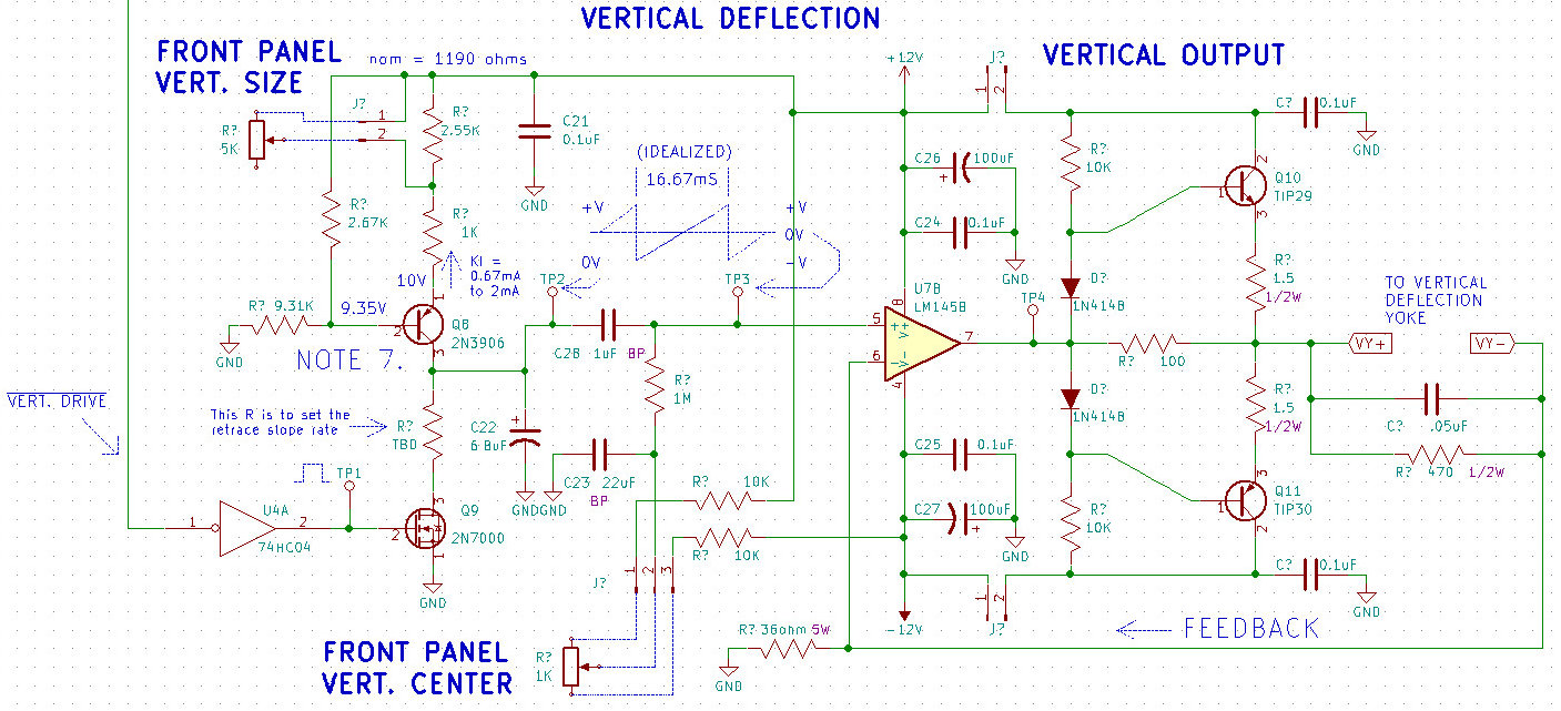
Vertical Deflection Schematic Diagram The vertical scan section is a conventional current source and switched capacitor ramp generator driving a high speed two transistor and op amp, "totem pole" output stage. HOW! absolutely appropriate for a project called The Chief! All puns intended! The active low vertical drive pules comes from the sync generator, is inverted and turns on the FET Q9. This discharges C22 which has been charging from the constant current source formed by Q8. It is adjustable between 0.67mA and 2mA for setting the scan size by way of the 5K front panel pot. The output of the ramp generator is AC coupled to the class A output stage through C28. A DC voltage between approximately +/-2 volts is summed with the AC coupled ramp to provide vertical centering. This is also controlled via a front panel pot. The output amp drives high current to the yoke of about +/- 100mA for scan and +/- 2 amps during retrace. The .05uF capacitor and the 470 ohm resistor form a damping network that swamps out the third and other harmonics that are generated in the yoke. These would appear as undesirable scan distortions. You will see ringing sine waves riding the scan currents. Yes, a good current probe for your scope is a must for debugging scratch built scan circuits. If you decide to copy these scan circuits, the horizontal too, be aware that a capacitor and resistor substitution box is a must! Be sure they are rated for KVs in the case of horizontal. The capacitor box should span from 10pF to 1uF in as many steps as possible for best results. These devices are how you obtain your resonance and swamping capacitor values for each individual yoke. All yokes are not created equal! And I'm not yoking! (GROAN!) [HOME] [ELECTRONICS PROJECTS] [THE CHIEF TOP] [NEXT PAGE] |