LabGuy's World: The Chief, Part 5 - Video Amplifier Chain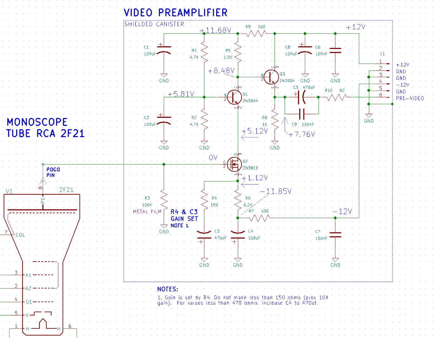
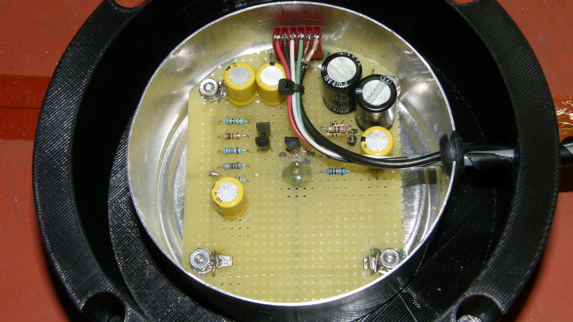
Video Preamplifier Schematic and physical assembly The video signal generated by the electron beam sweeping over the picture electrode is sent to the video preamplifier. This amplifer takes the very weak signal of the tube and boosts it into the range of about 1Vpp and drives it down a shielded coaxial cable to the video output processor where sync, blanking and DC restoration is performed before going to the output. The preamp consists of a FET input cascode amplifier. The signal at the collector of Q1 is buffered by Q3 which drives the cable. The FET, Q2, provides the extra high input impedance required to read the signal from the Picture Electrode, PE. Unlike a light sensitivie camera tube, the signal from this monoscope tube is quite strong at around half a microamp. This generates a voltage of 100mV on the 100K load resistor, R3. 
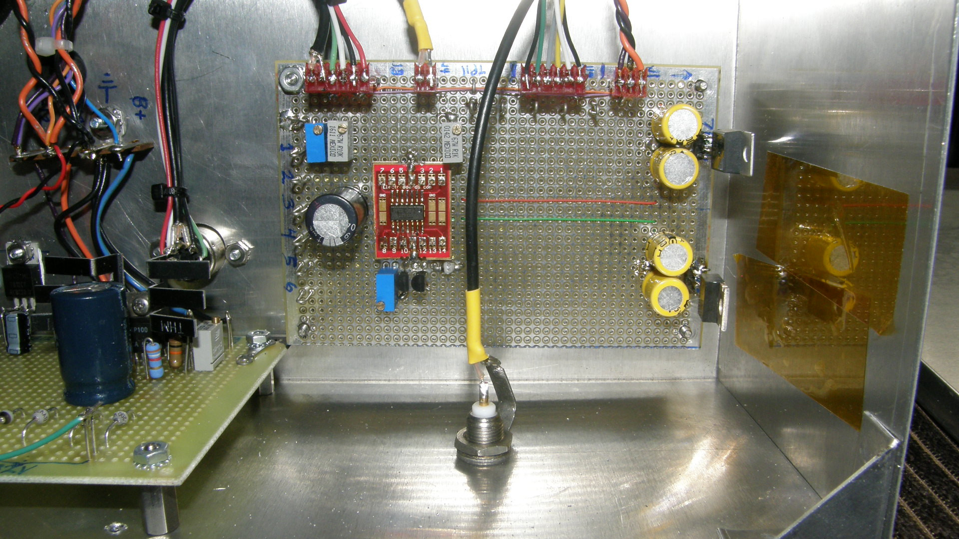
Video Output Processor Amplifier and physical assembly The output processor consists of several stages arranged in "a chain". First is the Gain and Equalization, which sets the proper raw video level and corrects for frequency roll off in the front end preamp. The input video level is set by way of variable resistor RV1. Next stage is the DC restoration. This clamps the raw video signal to a fixed DC level. In the case of the monoscope, it blanks to full white instead of black like a normal camera tube. So, the DC voltage that it is clamped to is just under 1 volt and is set by RV2. The clamp action is performed by FET Q1 which is turned on during the blanking period, charging the output side of capacitors C2A and B to the clamp voltage. There are two caps to accommodate the low and high frequencies separately. Following DC restoration is the video path blanking. This differs from beam blanking in that the tube may be blanked during this time, but the signal is very noisy. So, this step blanks and quiets the blanking period. After blanking comes the black clipper. This removes any spurious signals, like the glitch generated when FET Q2 switches from on to off. Last, but not least, is the output video driver and sync adder. Sync is sent over from the deflection board and is summed into the video signal by way of Sync Level control RV3. Sync is inverted on the deflection board because it is being "added" to the minus input of the op amp which inverts it again to its normal polarity. 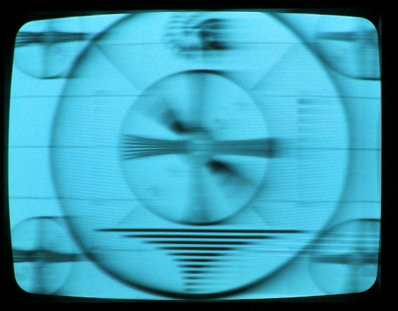
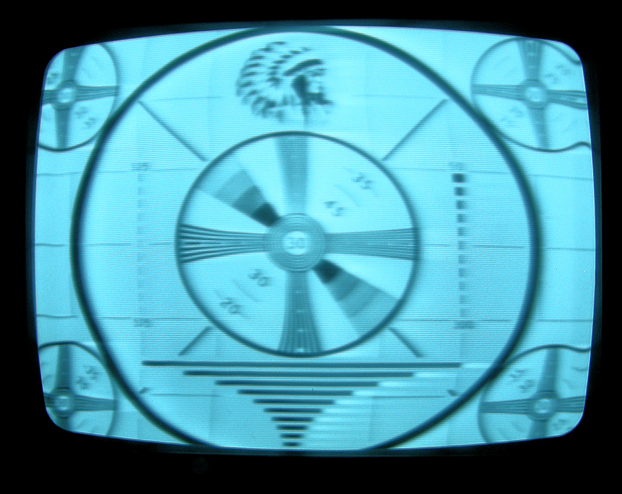
The image quality before and after adding the peaking circuit to the video amplifier (20190526) The original image from the monoscope was not very good. It had very poor high frequency response. For a month or more now, I have been busy working on the PhiloCam project. After getting together with a bunch of fellow antique television enthusiasts on May 18th, I came home with a suggested high frequency peaking circuit design. Thank you, John Staples. I modified the circuit slightly, as it was given to me from memory and instead, incorporated the exact circuit found in the original RCA TK-1B service manual. This was installed and the incredibly soft image was dramatically improved as seen in the two photos above. Please note: Most of the geometric distortion in the photo comes from my surplus store bargain video monitor! (Future photos will be taken on an LCD monitor which has perfect geometry by default.)The watery distortion is caused by the power transformers being too close to the monoscope tube. I have a fix planned for this problem too. Though this second image is far better than the first, there is still some more room for improvement. All that low frequency overshoot in the black horizontal bars at the bottom of the image, for instance. So, be sure to check back for updates in the future! 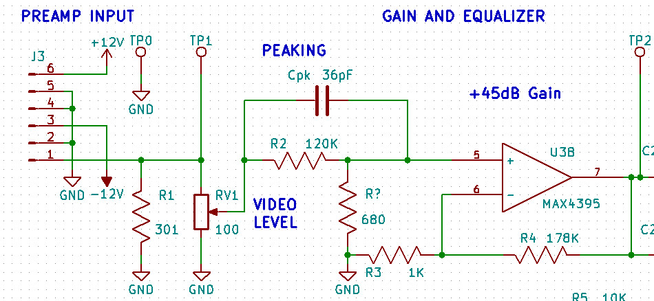
The peaking circuit added to the first stage video amplifier (20190526) The improvement of the video peaking is shown in the partial schematic above. The 120K and the 680Ω resistor drop the whole signal by 45dB (about 1/179) and amplifier boosts it back up by 45dB or about 179 times. The capacitor Cpk boosts the high frequencies in the correct ratio with the 120K resistor to create a relatively flat frequency response over the natural roll off of the stray capacitance effects at the video preamp input. The exact value of Cpk was determined experimentally by patching in a variable capacitor and dialing it in for the best image. Then I removed it from the circuit and measured it with my capacitance meter. A fixed value capacitor was then installed for Cpk. Adding the higher gain to the video amplifier stage has introduced an instability, not shown (yet), that causes intermittent black bars to flash across the screen. I will report the cause and the cure of those problems on the next page. [HOME] [ELECTRONICS PROJECTS] [THE CHIEF TOP] [NEXT PAGE] |