|
LabGuy's World: NBTV - 10-4 Eleanor RGBY Color Video Signal Generator
[HOME] [ELECTRONICS PROJECTS] [NEXT PAGE] [2. HARDWARE] [3. SOFTWARE] [4. IMAGES] [5. CONCLUSION] 1. INTRODUCTION 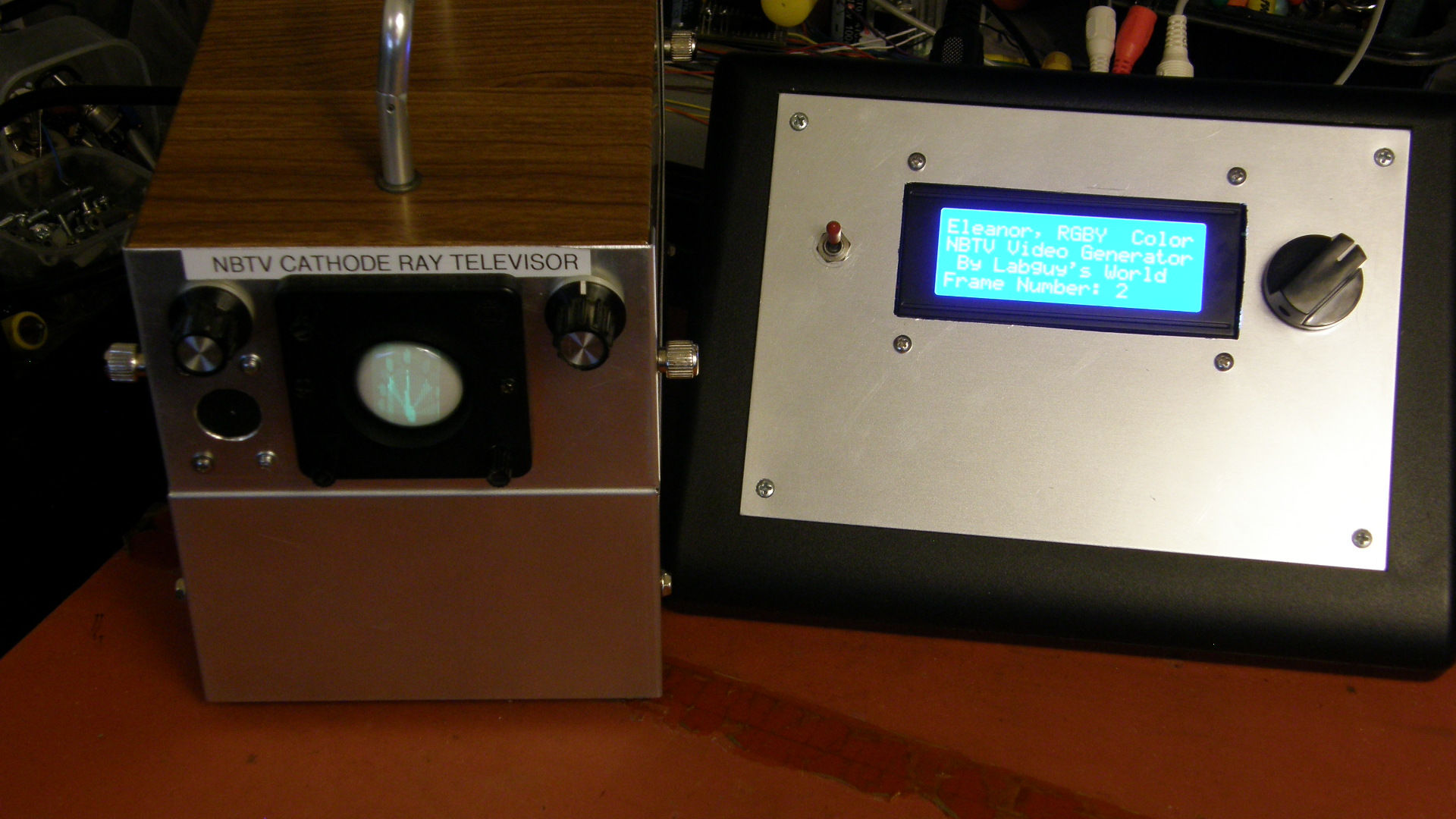
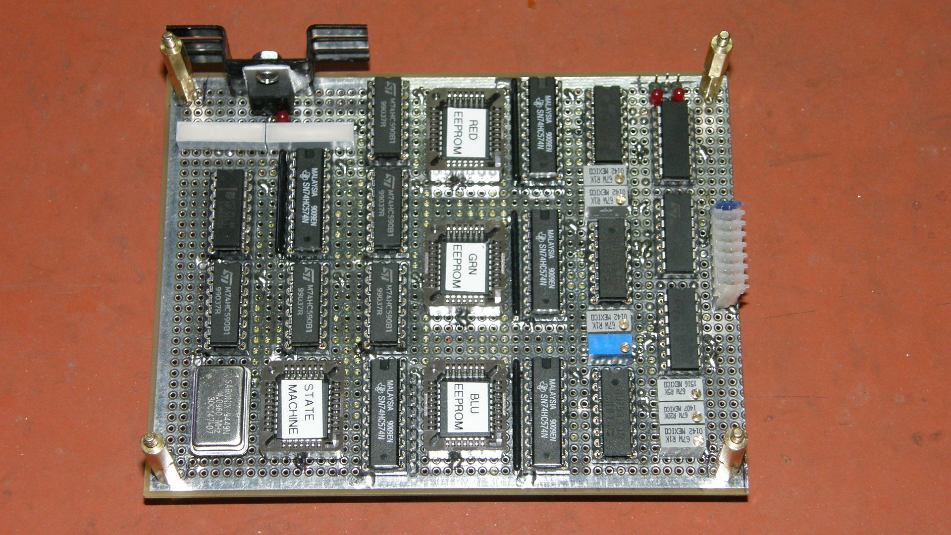
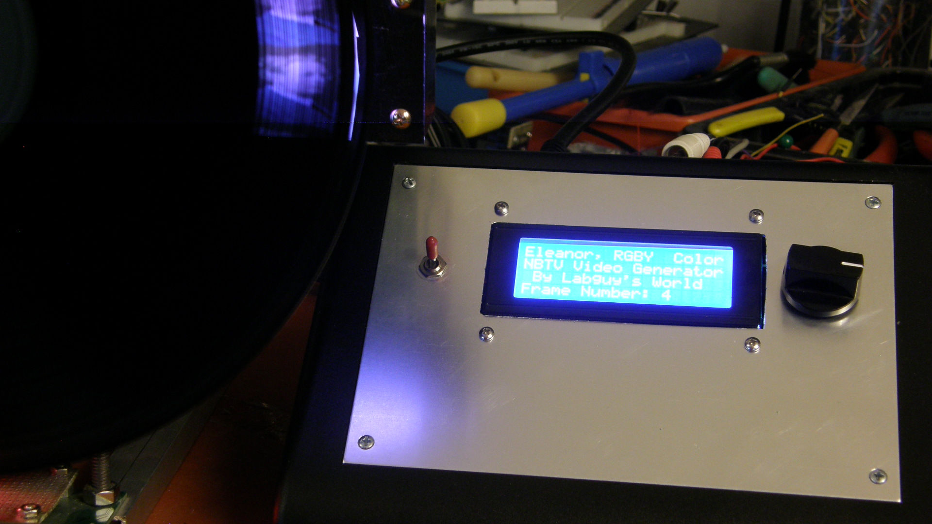
The 10-4 Eleanor RGBY Color Video Signal Generator 4 x 5 inch Hand Wired Circuit Board WHAT? The 10-4 Eleanor is an NBTV compatible video signal generator for television experimenters. WHY? This is my answer to the high priced ($1,050) Aurora Designs World Converter which is no longer available any way. HOW? Did I come up with the name? From the output signal abbreviationsm "RGBY". Thanks John, Paul, George and Ringo! WHERE? At Labguy's World, of course. WHEN? Right now. Let's go! In the three photos above, we are looking at the best NBTV project to come from my lab up to now. The first photo is of the Eleanor driving my monochrome Cathode Ray Televisor. The second photo is of the main hand wired video circuit board. The third photo is of the Eleanor driving my full color BIG Televisor. Yes. That is a colorized photo of John Logie Baird proudly on display. The 10-4 Eleanor produces a 100% NBTV compatible video signal in both monochrome and color, is relatively simple to construct and relatively low cost as well. Any modestly experienced electronics enthusiast should be able to successfully copy this design. The Eleanor produces a fully compatible NBTV video signal as defined on the NBTV organization web site. The Eleanor can store 256 color images in her internal memory. The Eleanor produces both a black and white (monochrome) CVBS (compostite video blanking and sync) signal for use by televisors, recording or transmitting devices AND includes simultaneous Red, Green and Blue video outputs for colorized Televisors. Operation could not be simpler too. Turn it on, rotate the selector to the desired image. That's it. With a well stocked junk box, the Eleanor can be constructed for less than $100 and if an experimenter purchased absolutely everything retail, the cost should still be well below $300. Which, one must admit, is a very low price for a professional quality video signal generator. At the end of this article, there will be provided premade default binary image files and the binary code for the system timing EEPROM. Software tools will also be provided for creating the default initial EEPROM contents, adding one's own images as desired, and modifying the state machine timing EEPROM. Also, the full schematics, layout, timing diagrams and block diagrams will available as PDF and archived Kicad files. NO PCB has been laid out at this time. If response is strong enough, I will consider having PCBs manufactured. But, for now, this is a luxury expense we can avoid. I have not been satisfied or impressed by the available NBTV signal sources that are freely available. They certainly do the job. But I thought I could do better. So, I took it upon myself to design a simple frame buffer that could hold a lot of images and produce an NBTV compatible video signal, in both color and black and white. A true video signal source that meets my rather stringent signal quality requirements, is relatively simple to duplicate and won't break the bank. This project achieves all of those goals. 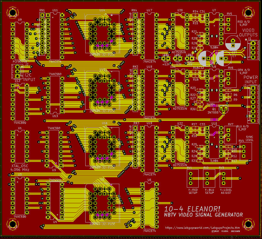
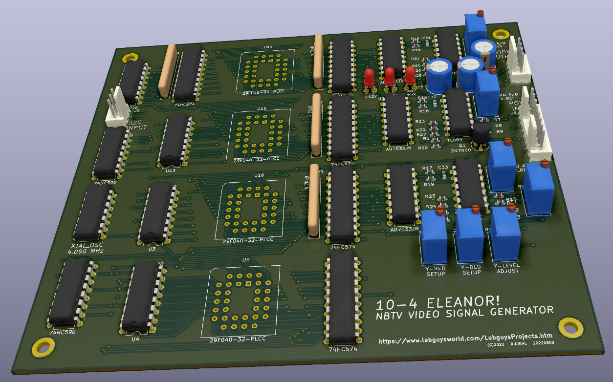
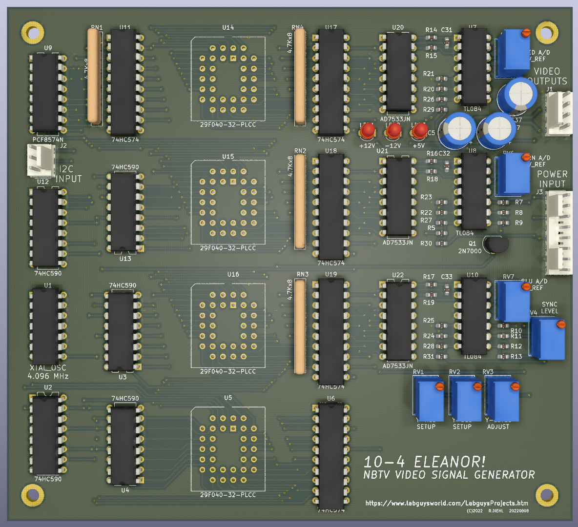
The 10-4 Eleanor RGBY Color Video Signal Generator 5 x 5-1/2 inch Printed Circuit Board Recently, I laid out a circuit board for the 10-4 Eleanor's video generator. This is a four layer board. Layers 1, 3 & 4 are ground and signal layers. Layer 2 is reserved as the power layer and distributes, mostly, the +5V for the digital parts. The analog +/-12V is routed in this layer as well. The power layer is well shielded between two ground layers for low noise operation. All bypass capacitors are located on the back side of the board adjacent to the via that feeds power or ground to the chip on the opposite side of the board. All SMT parts are passive 0603 with pads laid out to accomodate easy hand soldering. The images above are the screen shot of the board in Kicad and two 3D rendered images of the board. The renderer did not have a model for the memory chip sockets. That is why those four locations are not populated. The quality of the rendered images is outstanding. FYI: [My PCB tool is Kicad 5.1.7]. When I uploaded the files to [OSH Park], the estimated cost for three boards was over $400, or about $134 each. This is before the cost of stuffing the parts. I did NOT order any boards (yet). Whether I do or don't will depend on the response from my readers. Please [drop me a line] if you are willing to cover the cost of a blank board of your own. [HOME] [ELECTRONICS PROJECTS] [NEXT PAGE] [2. HARDWARE] [3. SOFTWARE] [4. IMAGES] [5. CONCLUSION] |