LabGuy's World: The Chief, Part 1 - Mechanical Construction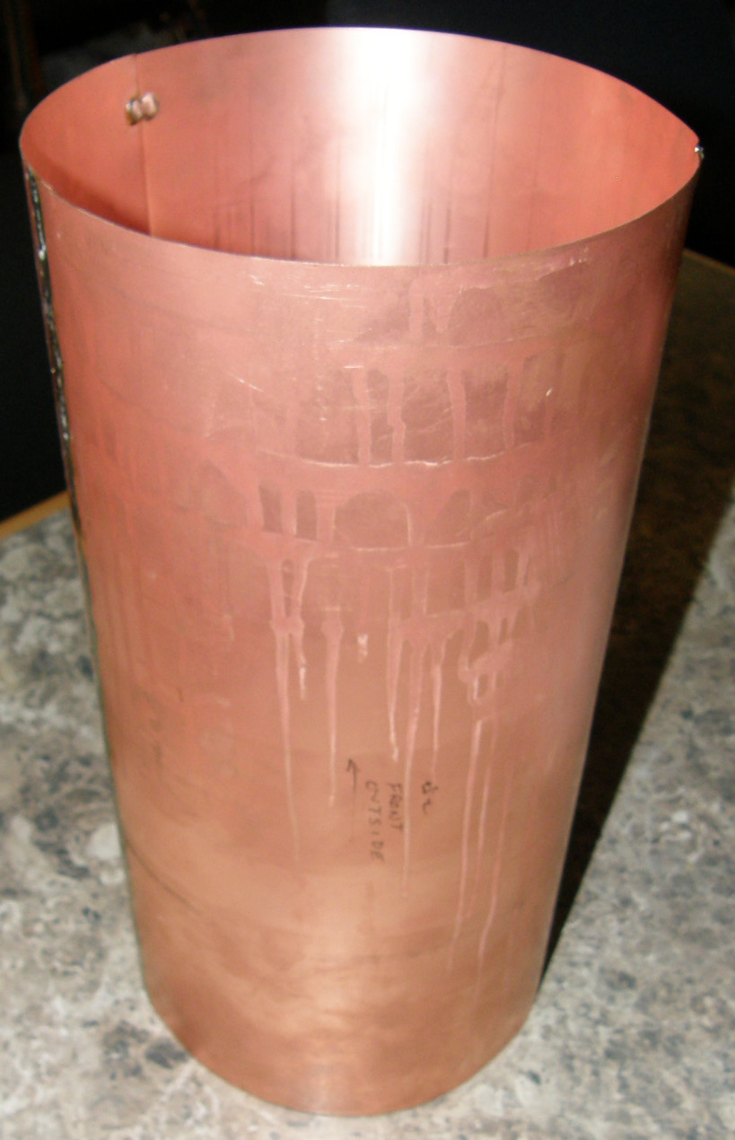

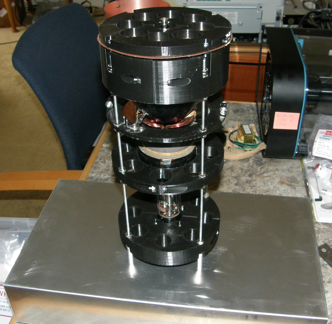
A Faraday shield for the monoscope tube We need to shield the monoscope tube from outside interference. I made this copper cylinder from very thin double sided circuit board material. A thin layer of fiberglass is sandwiched between two layers of copper foil only a few mils thick. I curled this around an empty coffee can and soldered it together at the seams. It will operate in the up right position as shown. The shield is 12 inches tall with a slightly larger than 6 inch inside diameter. I provide the physical dimensions of the 2F21 to help you get a sense of the size of the shield. Or you can view the entire RCA 2F21 datasheet. A series of round support shelves are 3D printed and stacked with four upright threaded rods. This structure supports the monoscope tube, the deflection coil, side and front electrical contacts as well as the tube socket. The shield slides over the top of it all and an RF tight top cover goes on top of that. The threaded rod and locking nuts scheme allows very fine positioning of each level relative to the other. Mainly for postitioning the defelction yoke and the Collector Contact connection. The lowest level supports the all-thread rods and conains the tube socket. 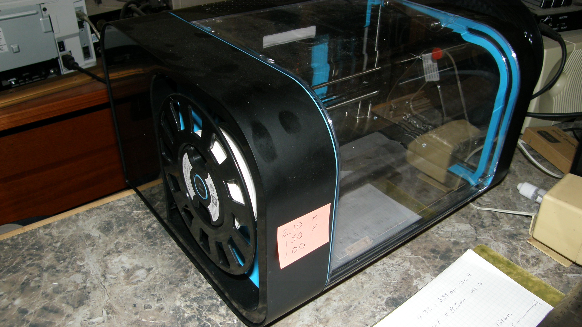
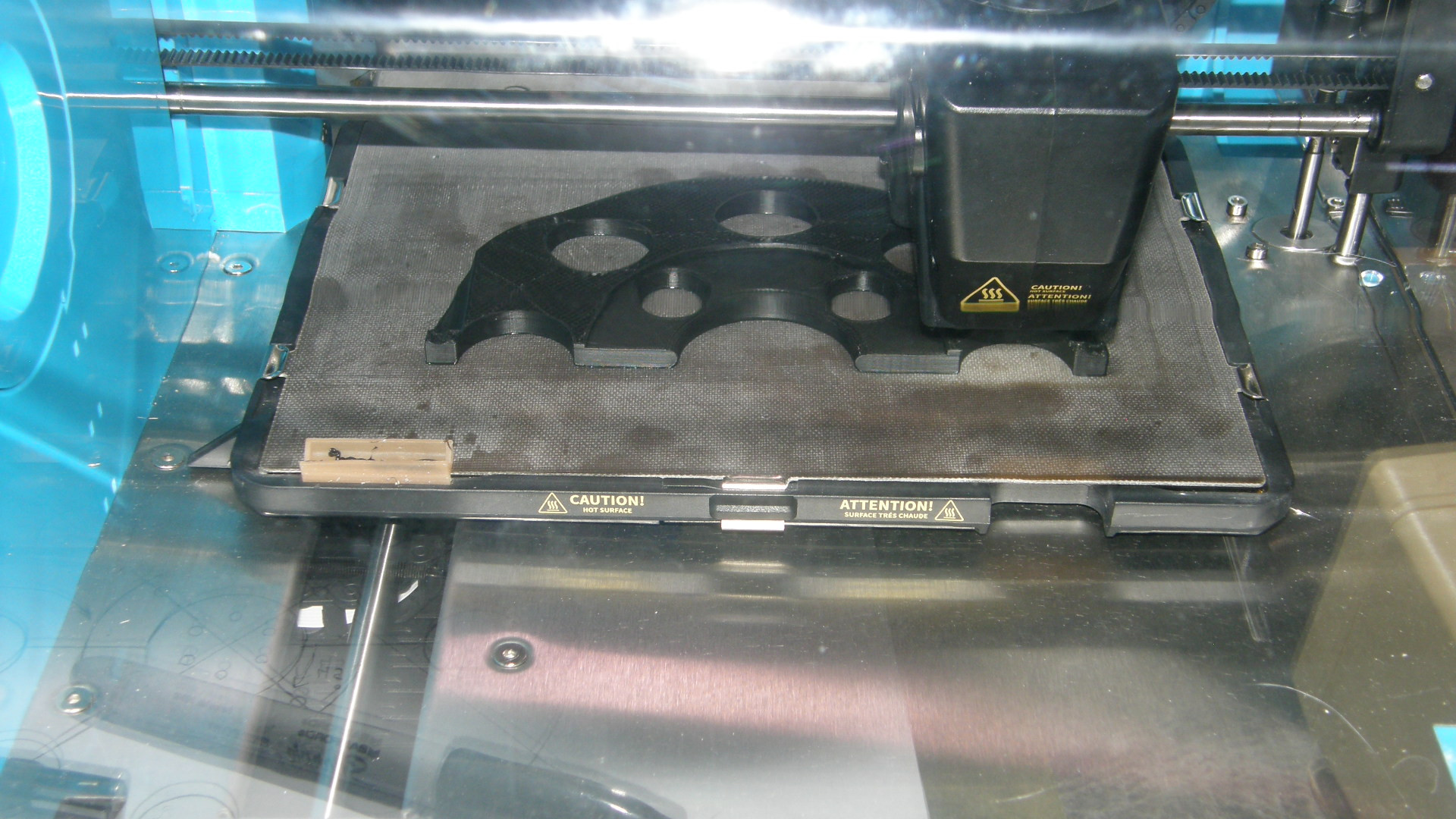
A brand new 3D Printer to make it all happen! The newest member of the team here at Labguy's World is the CEL Robox 3D printer. This opens a whole new world of possibilities. With one serious caveat. It can't make very large parts. The build volume is just 8 inches by 6 inches by 4 inches or 210 x 150 x 100mm. The parts of the shield and tube supports are too big to print in one piece with this compact machine. So, I split them into two halves and life goes on. You can see the first half of the deflection yoke support being printed. 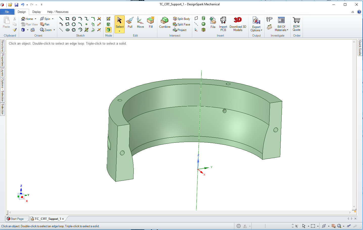
All of my parts are created in DesignSpark Mechanical This tool is free to download and works very well. Needless to say, I was not immediately productive. Watched many DesignSpark Mechanical tutoring videos. Several times each. After a couple of days, I was producing functional parts. Mostly. We won't talk about the box of reject parts or, as I like to call it, my box of shame! I truly hate wasting material. Especially if I have to pay for it. So, we will log those costs on the books under, "educational expenses", just like the part pictured above! 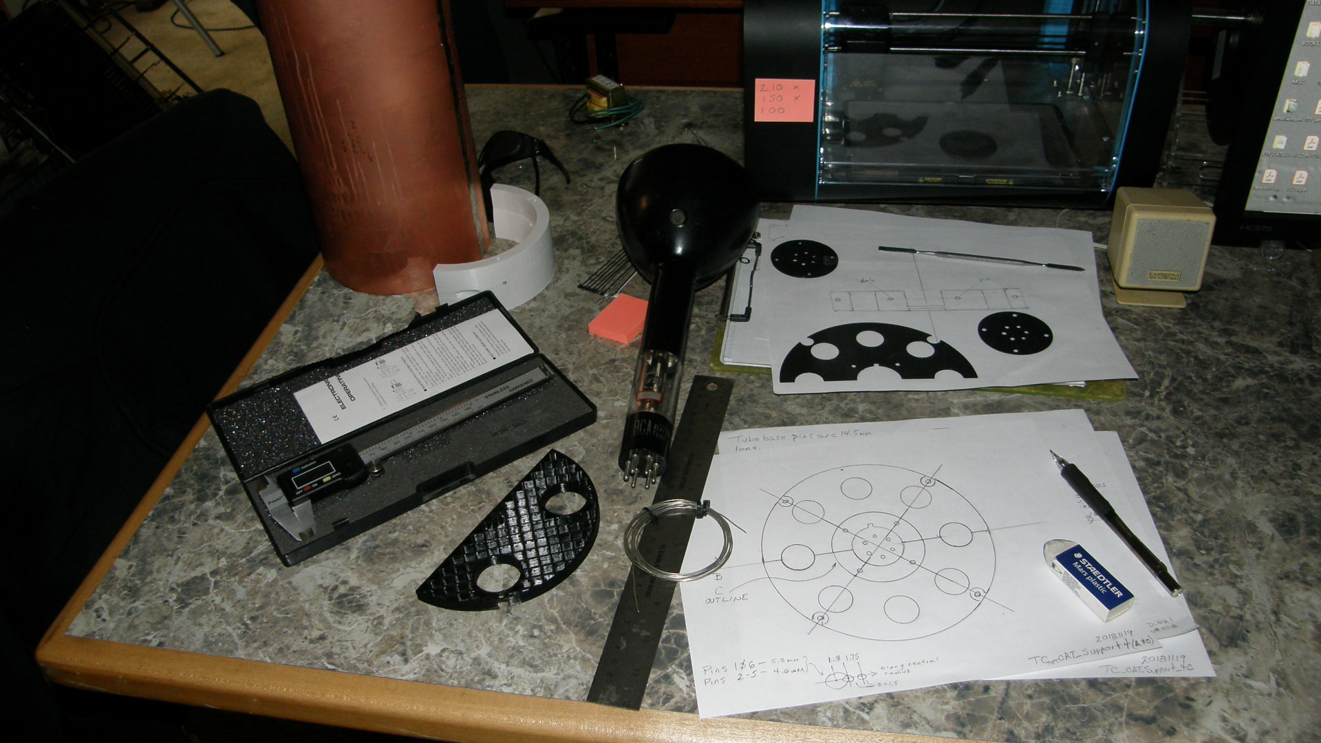
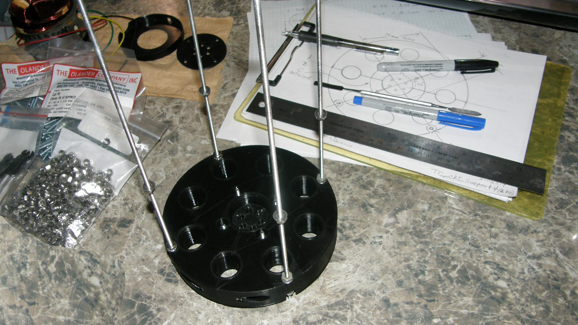
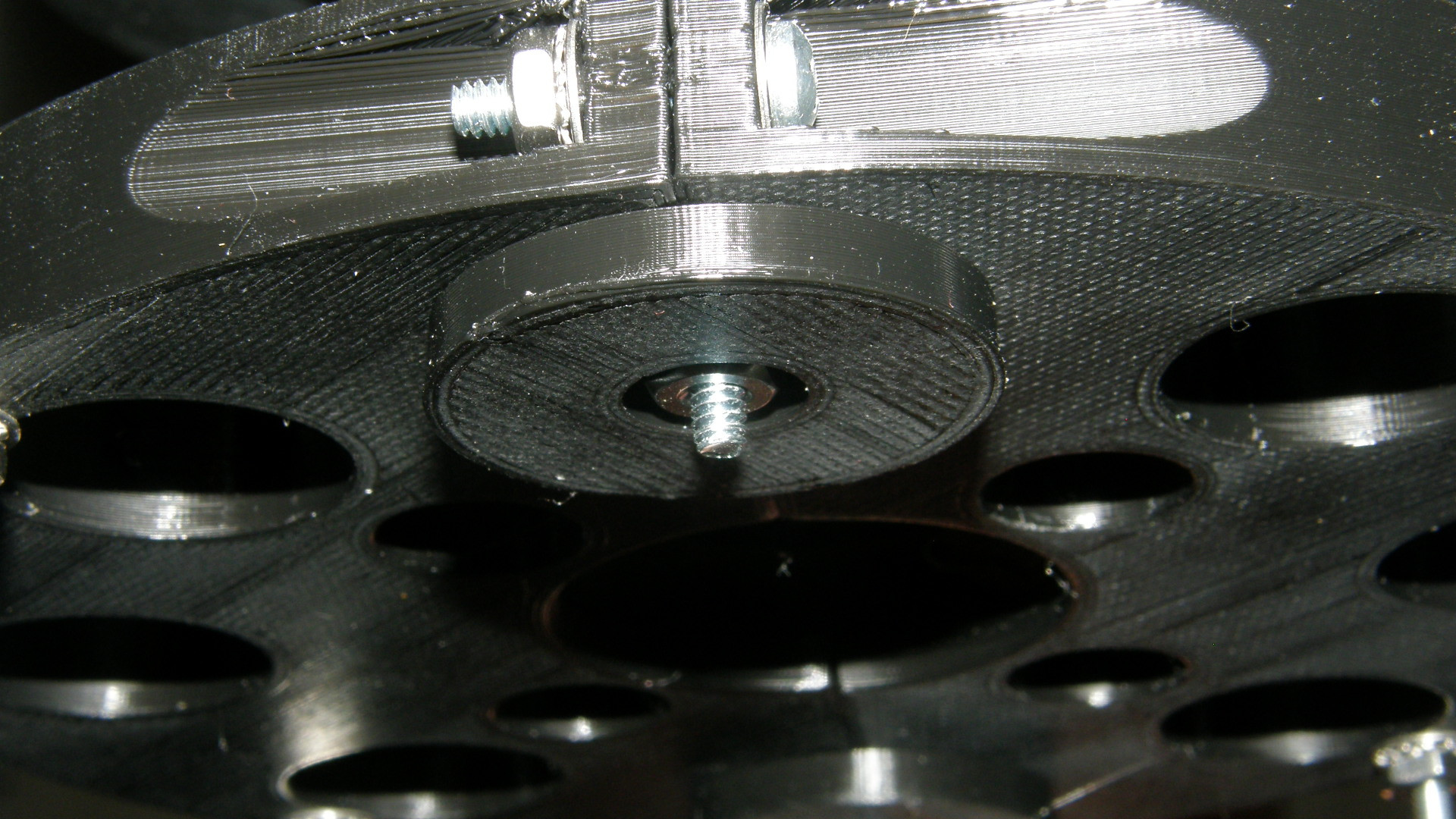
From concept to physical reality 20181119 These images convey my journey from the early creative phase to a functional component. I was even able to design my own special low insertion force tube socket! In the photo on the right, we see the base of the support frame. In the center of that is my custom made tube socket. Since there are two monoscope tubes in my collection, and other collectors may wish to test their tubes, the system is designed for easy tube swapping. The base unit is comprised of two half round base supports and a replaceable tube socket. In case I want or need to make changes to it. The two half rings are fastened together by inch and half long #6-32 pan head screws with flat washers and kep nuts. I can barely believe how amazingly strong this part feels! With the socket installed, the two rings are fastened with four more #6-32 screws making the strength ridiculous. Just the way I like it. Here is the answer to question that must be burning your mind. How long did it take to print everything you see here? I'm glad you asked! The three parts of the base took over 18 hours to print. The two ring halves were 8 hours each and the tube socket takes just over two hours. 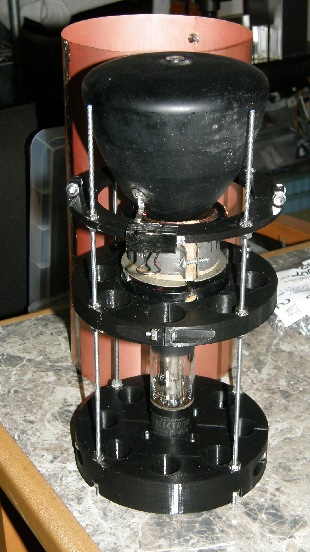
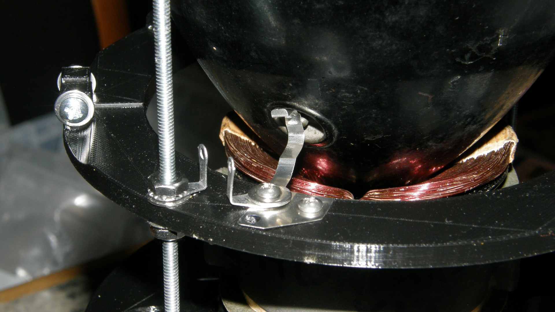
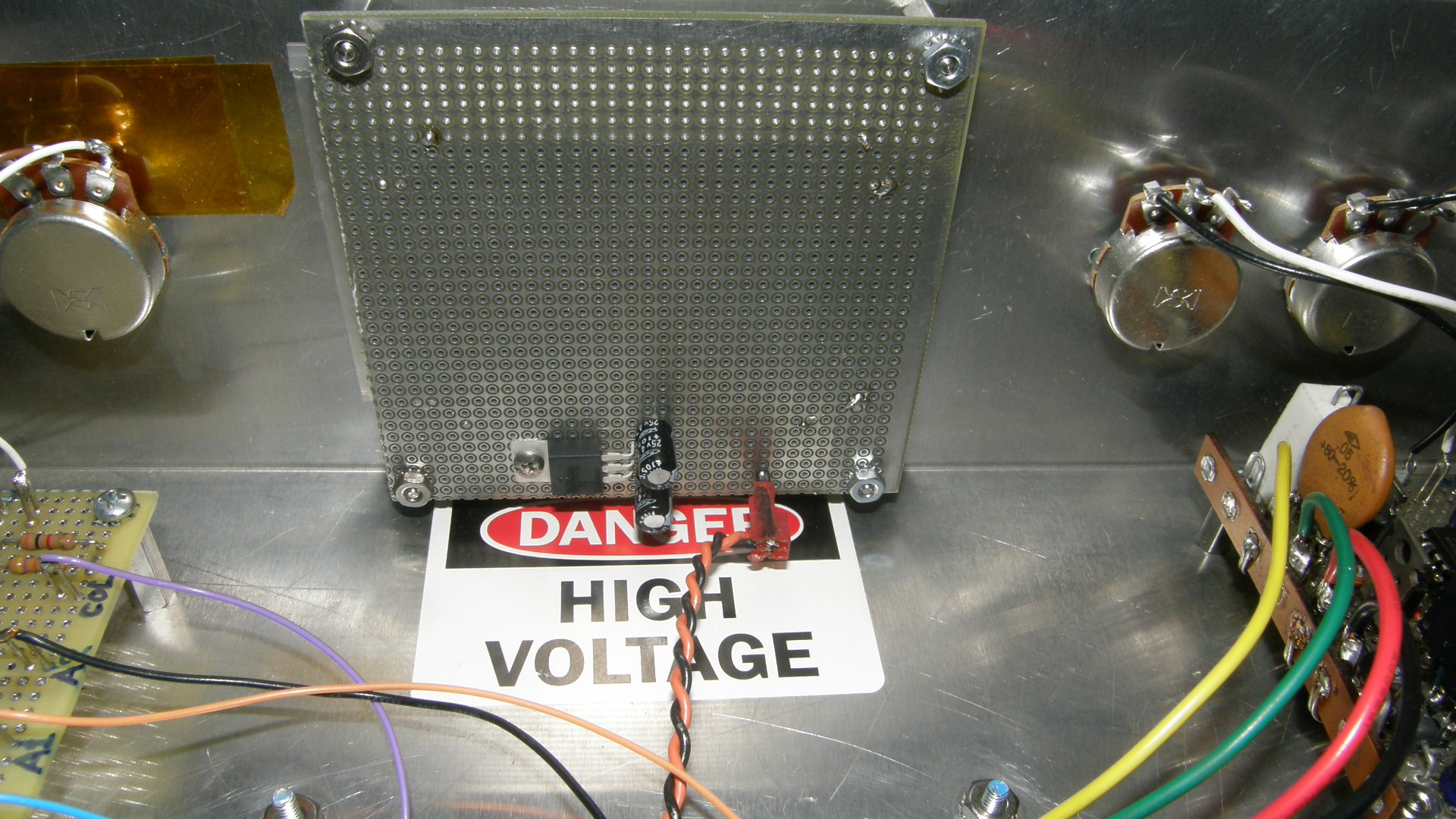
Progress as of the day after Thanksgiving - 20181123 In the photos above, we see the addition of the deflection yoke support frame and the Collector Contact support ring. The contact is being held with the big paper clip in photo #1 and in its final installation in photo #2. Note the location of the solder lugs for receiving the signal conductor and supporting a future noise bypass capacitor. This electrode will be operating at around +50 volts DC at literally no current. (This is NOT a 2nd anode connection as found on conventional CRTs) The threaded rods are conveniently at chassis ground potential. 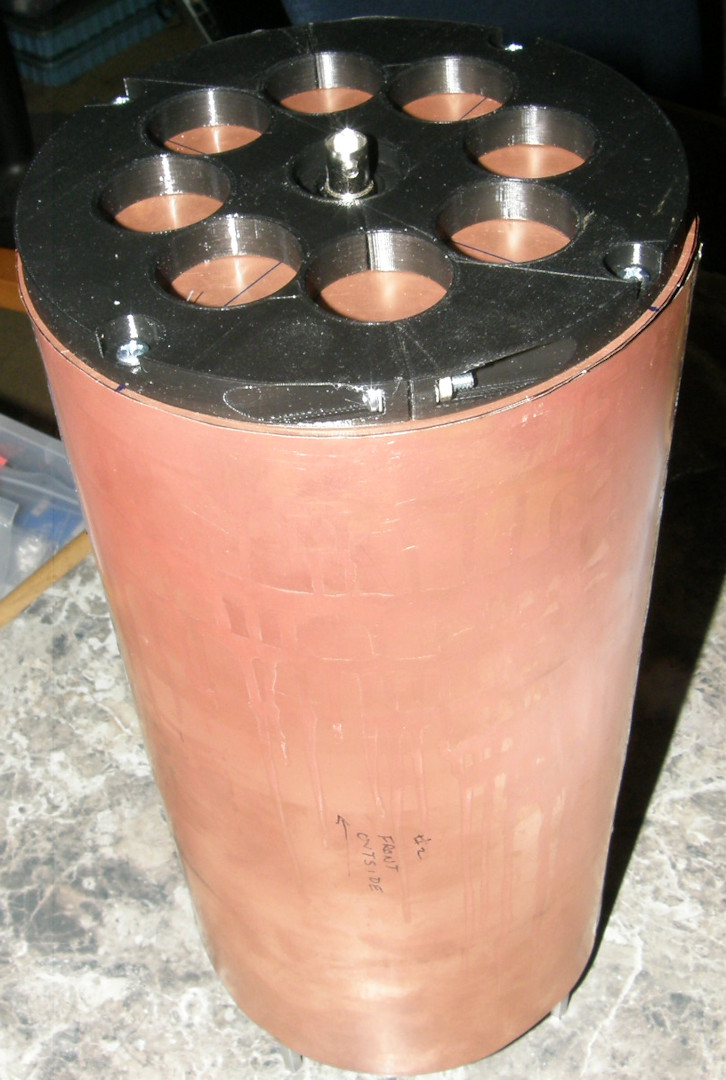
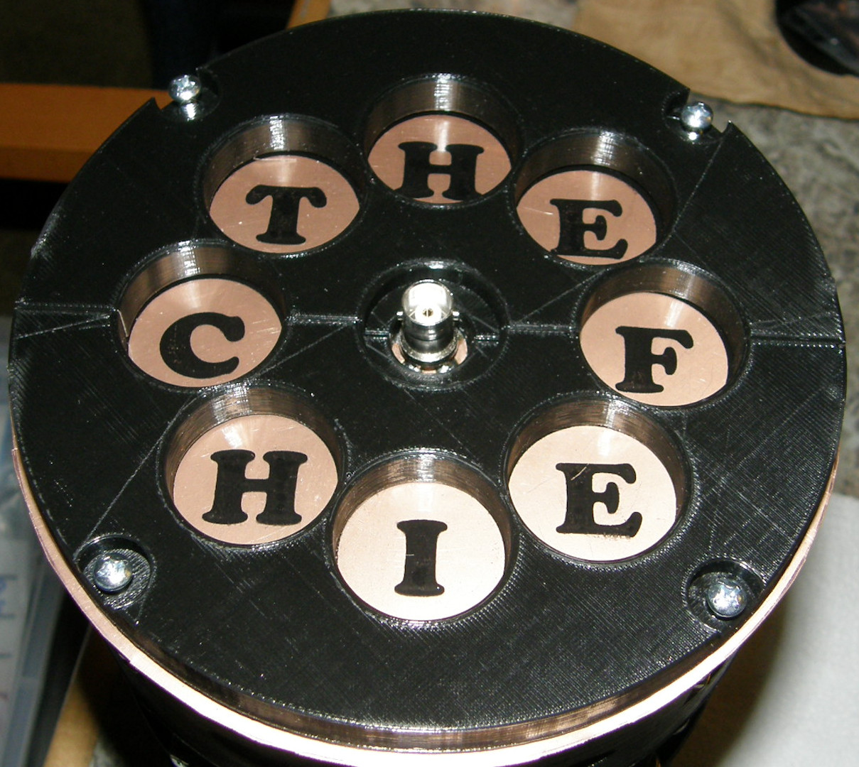
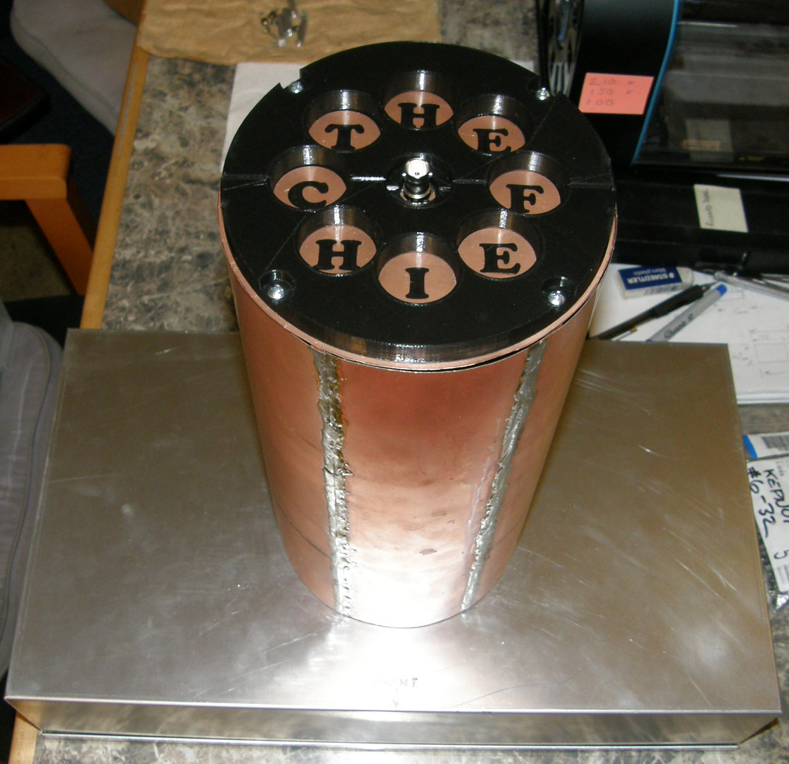
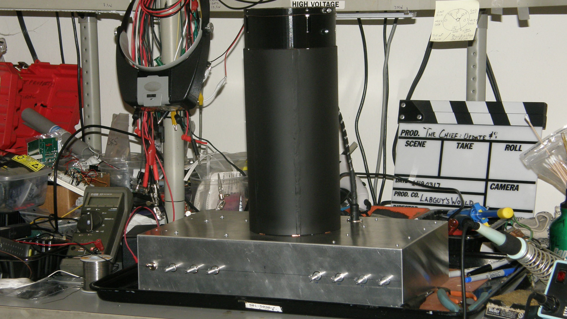
The Faraday shield and its support structure is nearly complete - 20181126 The top cover consists of the copper disc and its printed plastic support. The copper cylinder is 12 inches tall and 6 inches in diameter. It slips over the support frame and is secured by the top cover which is held in with four screws. The round cut outs were intended to preserve material and provide a handy finger grip for lifting. A printed transparent label sandwiched between the plastic and copper adds some much needed pizazz! (Don't worry. I have ideas for more.) The next step is to attach the support frame to the aluminum chassis and then secure the deflection coils. The chassis box is 18 x 10 x 4 inches (460 x 254 x 102 mm) This will provide lots of room for everything while providing the lowered center of gravity to compensate for the top heavy monoscope support frame. Fortunately, during construction, having the tube out of the frame makes it very light. As well as safer for this rare tube. 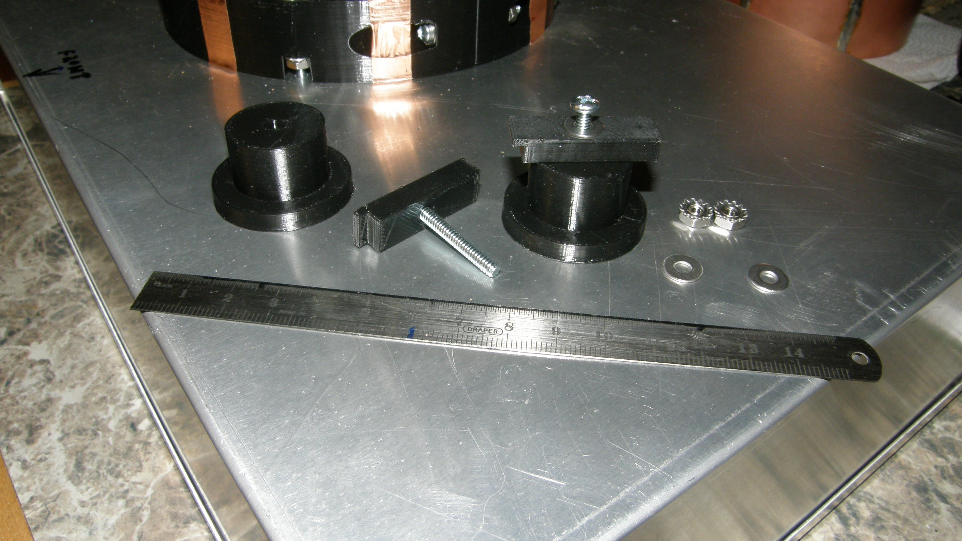
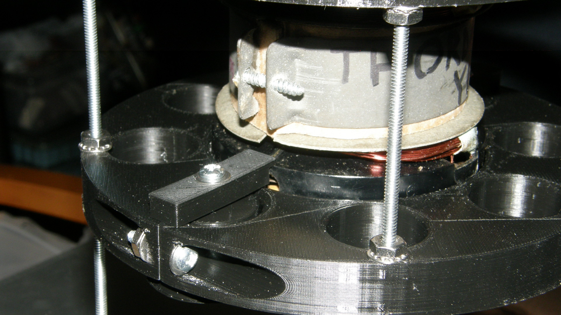
Securing the deflection yoke - 20181127 Up to this point, the deflection yoke has been unsecured in its cradle. With its leads temporarily removed, it is also free to rotate a full 360 degrees. With the monoscope tube removed, there was absolutely nothing holding the deflection yoke in place. The entire unit must be able to tolerate being completely inverted during construction. So, I created a pair of clamping blocks to secure the yoke, one on each side. By designing these two mounts to use the wire way holes already present in the support disc, the clamps can be positioned where it is convenient. This will be determined by the deflection yoke's final rotational position. Earlier in the day, I took time to realign the support structure. It was leaning due to an accumulation of forces as I loosened and tightened various of the locking nuts on the structure over time. It was twisted and pulled to one side. I noticed that the copper canister would not sit flat on the aluminum chassis and that the top plastic ring was also not level with the cylinder. All of this was loosened for the final time, I hope, and measured very carefully before securing everything for the last time. It all fits together nicely now. 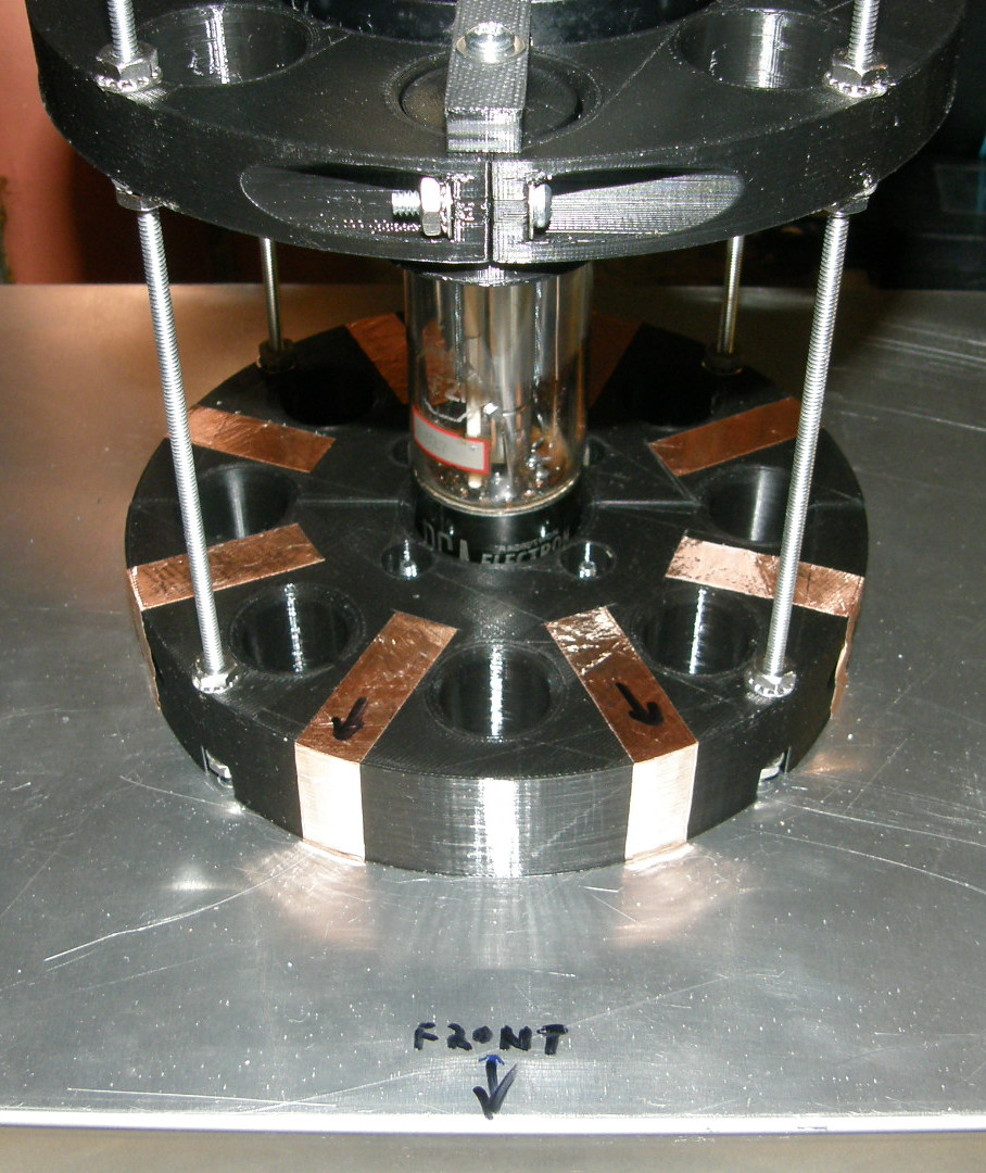
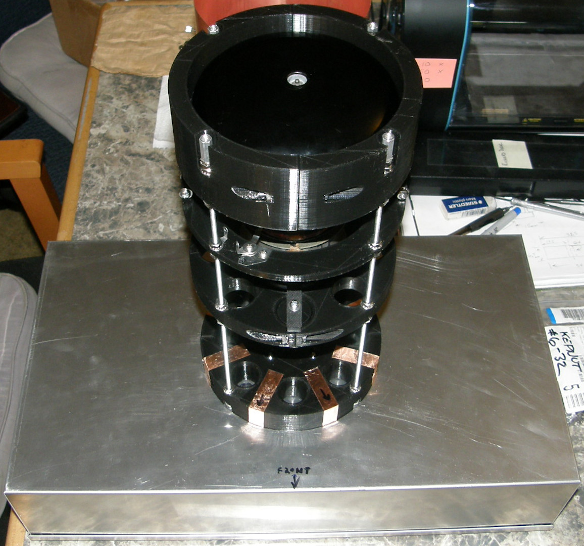
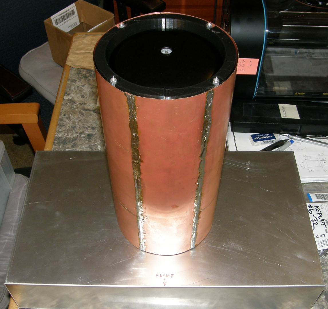
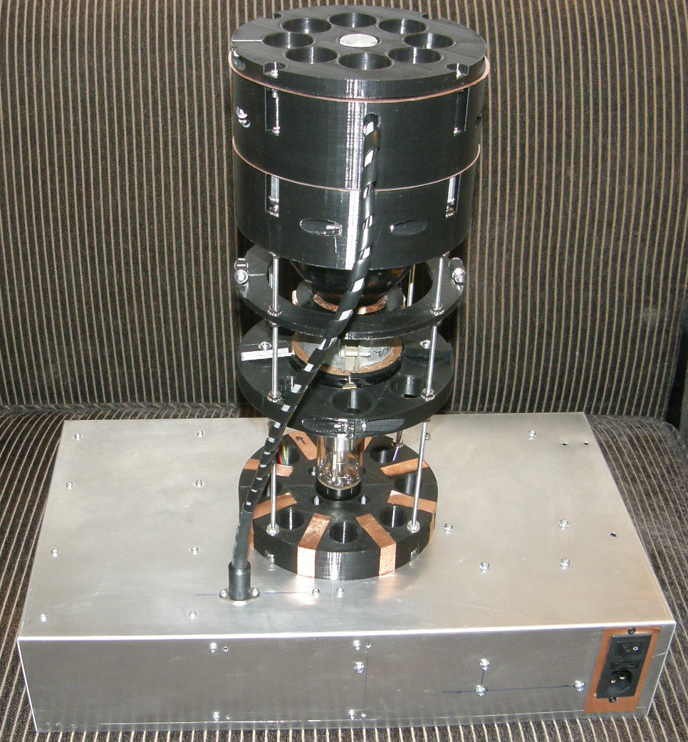
The Faraday shield in a bit more detail - 20181128 In photo #1 we see the copper tape that makes the primary grounding connections to the bottom inside of the shield cylinder. The arrows indicate the front of the unit. Ground is also carried to the top of the stack by the four threaded rods. The last piece to install on the cylinder will be an RF gasket around the inside of the top rim of the cylinder. This will positively connect ground to the top cover and seal the any gap that would form there. The idea is to keep out AM radio stations and other transmissions operating in the DC to 4.2 MHz region of the spectrum. The RF gasket will be added only after the outside of the cylinder is painted. The top cover also gets connected to ground through the mounting screws. When it comes to grounding, there is never enough. It should be of the lowest impedance achievable and the container should block as much RF interference as possible. Think "man hole covers" and "crow bars". The second photo gives you an idea of the size of the entire project now. It stands almost 18 inches tall. The broad base of the aluminum chassis gives it stability. We don't want this gem to tip over acccidentally. Nine rubber stick-on feet make the base solid to the table top. I'm thinking of painting the copper shield jet black. Not sure what color, if any, to paint the chassis. But, I am open to suggestions. Photos #3 & #4 show the shield and cover in place for normal operation. The BNC connector in the top cover makes contact with the monoscope Signal Electrode contact by way of a small spring contact. Yet to be perfected. The aforementioned RF gasket will make the business end of the cylinder RF tight at the top. The tiny gap near the bottom end is not nearly so critical. The output of the tube will be routed via a coax terminated in BNC connectors. It will connect the tube to the input of the video preamplifier. 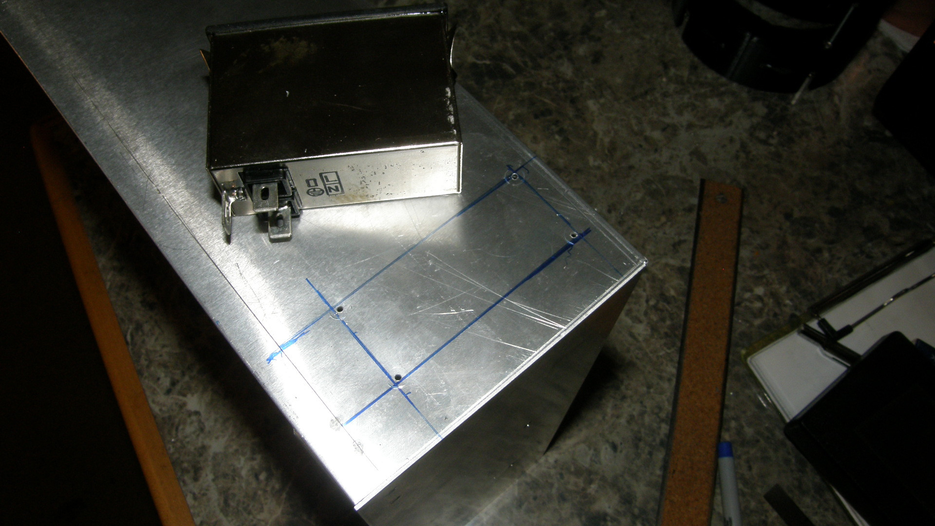
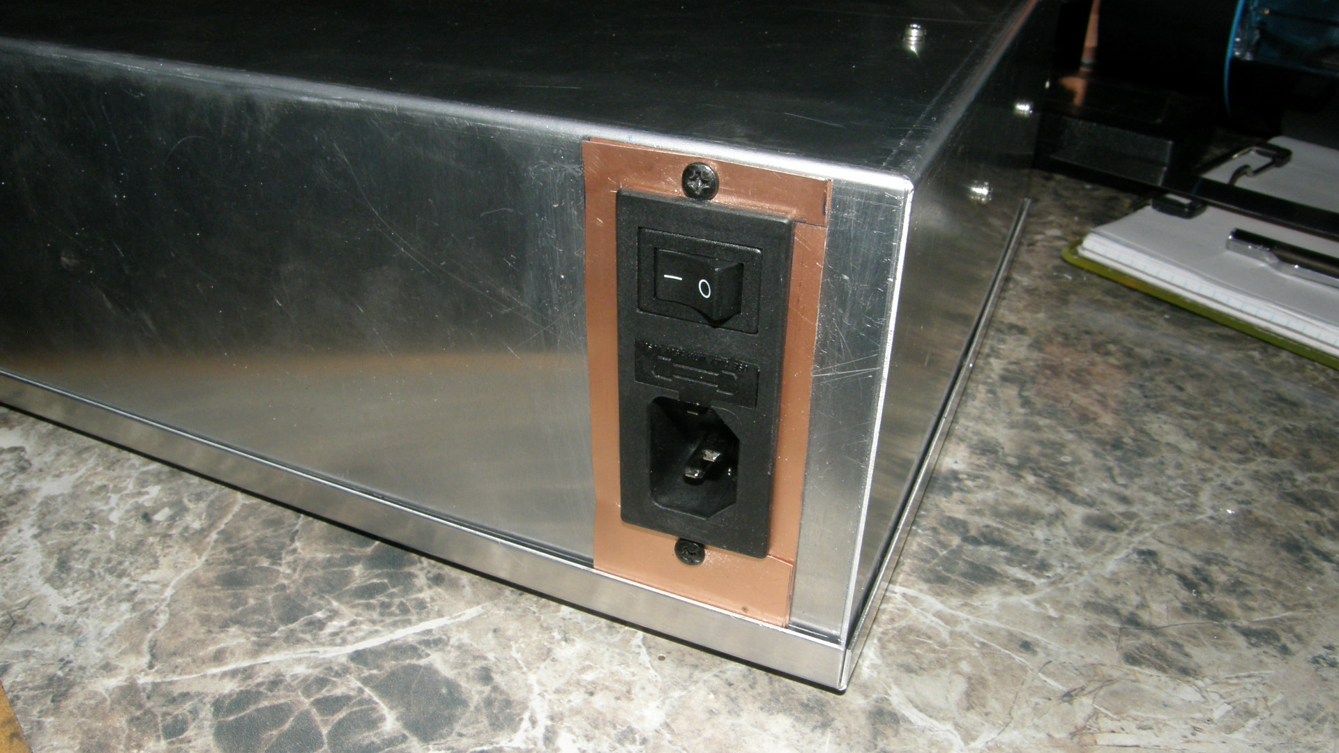
AC entry module and DC power supply are installed - 20181130 After cutting the hole, the AC entry module was a bit loose and wobbly. OK. More than "a bit". As you can see, I transferred the outline to the inside by drilling guide holes and still managed to make the hole slightly too large. Oops. The reason for this is that the nibbling tool (knuckle buster blood blister maker) won't fit inside the box and still be able to operate. So, the cutting must come from outside the box. To be accurate the outline has to be accurately transferred to the inside. An error prone process for sure. The damage was done. Oh, well. So, I cut some overlapping copper clad shims, anchored them solidly with sheet metal screws, and the recepticle was nice and tight to the chassis. It's not as pretty as I like. But, its also not as ugly as it could have been. I will give this simple solution a resounding, "Winner winner, chicken dinner" or an, "I planned it this way all along"! 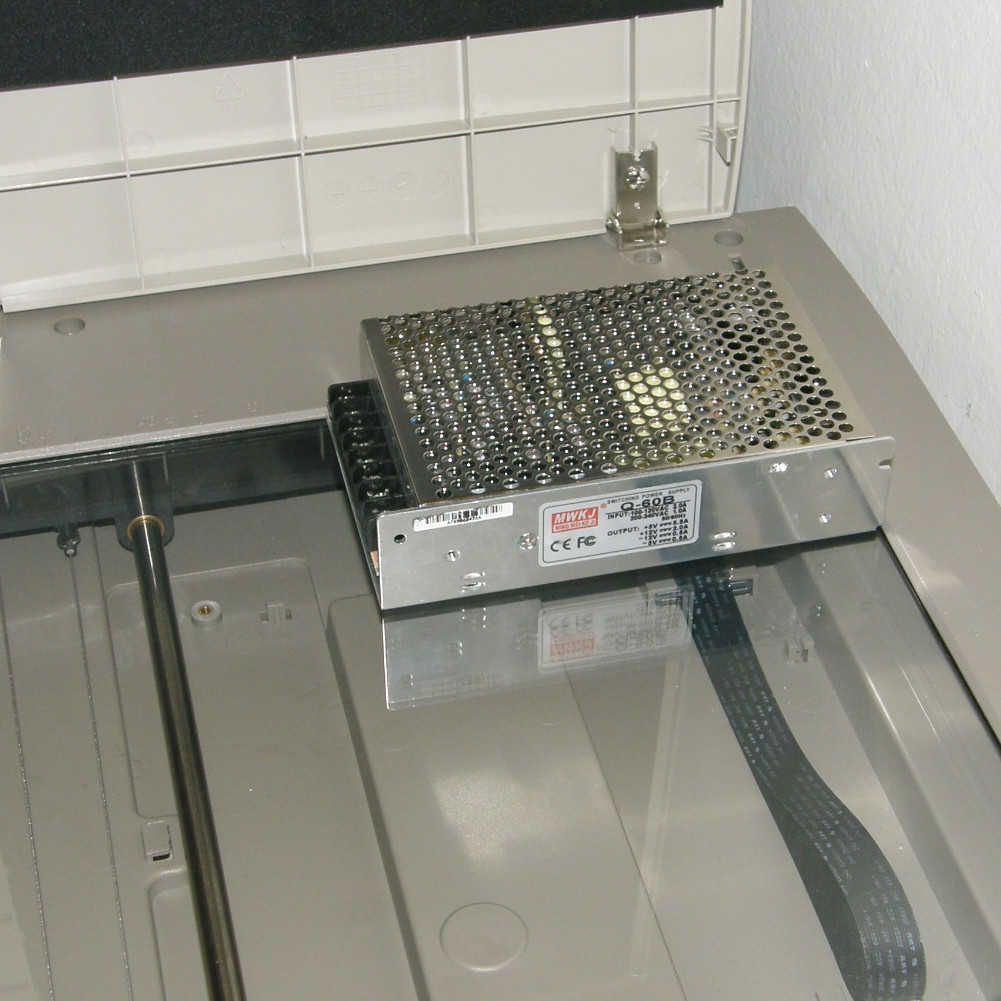
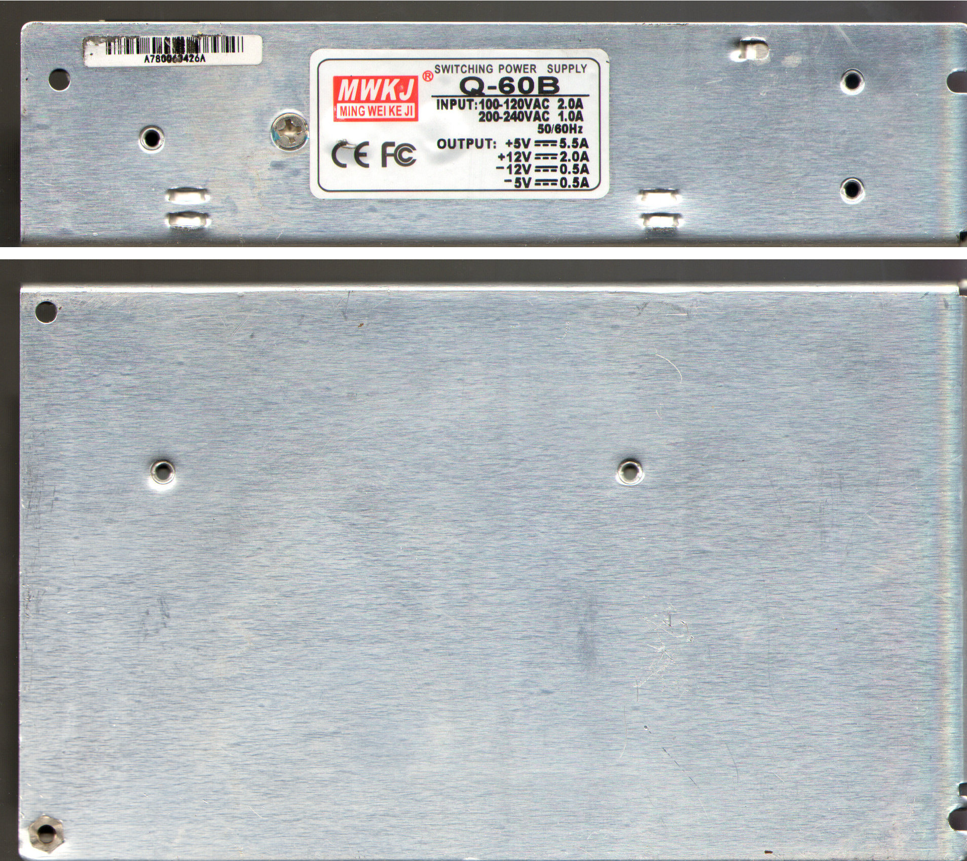
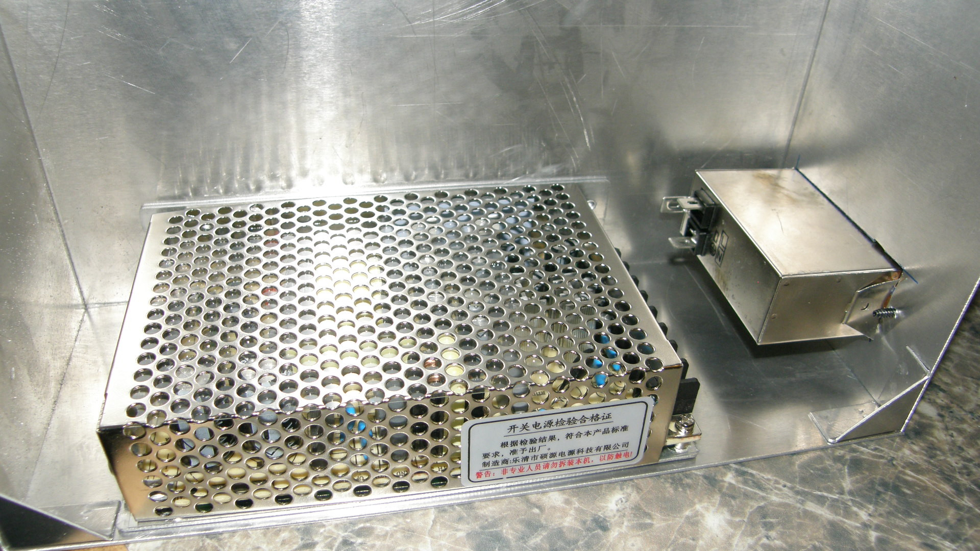
How I mounted the (FIRST) power supply inside the chassis - 20181202 I had much better luck with mounting the low voltage DC power supply. I put the actual unit on my flat bed scanner and scanned it at 300DPI. Essentially, I took two actual size photos of the darned thing. Second photo above is a composite image of both scans. I then laser printed the images separately at 1:1 scale, cut them out with scissors and taped them to the chassis as a drilling templates. Positioning the two stencils relative to each other, around the 90 degree bend of the chassis, was more art than science. Good thing I have "a calibrated eyeball"! Luckily, this worked very well. Only two out of five holes had to be slightly "adjusted". That's a bull's eye in my book! Since the power supply conforms to metric dimensions, it is attached with five 2.5mm screws. See in the last photo how the power supply tightly hugs the inside two edges of the enclosure. This provides the largest surface area possible for heat conduction to the outside of the box for dissipation. When the project is completed, I will add heat sink compound between the supply and the case for maximum heat transfer. I am hoping to avoid adding a fan. Total power dissipation for The Chief is estimated to be less than ten watts. AC wiring will commence when the front panel power control switch arrives from Antique Electronic Supply. It is a three potion toggle switch providing Off, Standby and On modes. It was originally intended for use in a Fender guitar amplifier. The switch on the AC entry module will be the primary power switch. But, the unit can also be turned on and off from the front panel. In standby mode, only the monoscope tube heater is powered. This gives a vacuum tube product Instant On! ability. 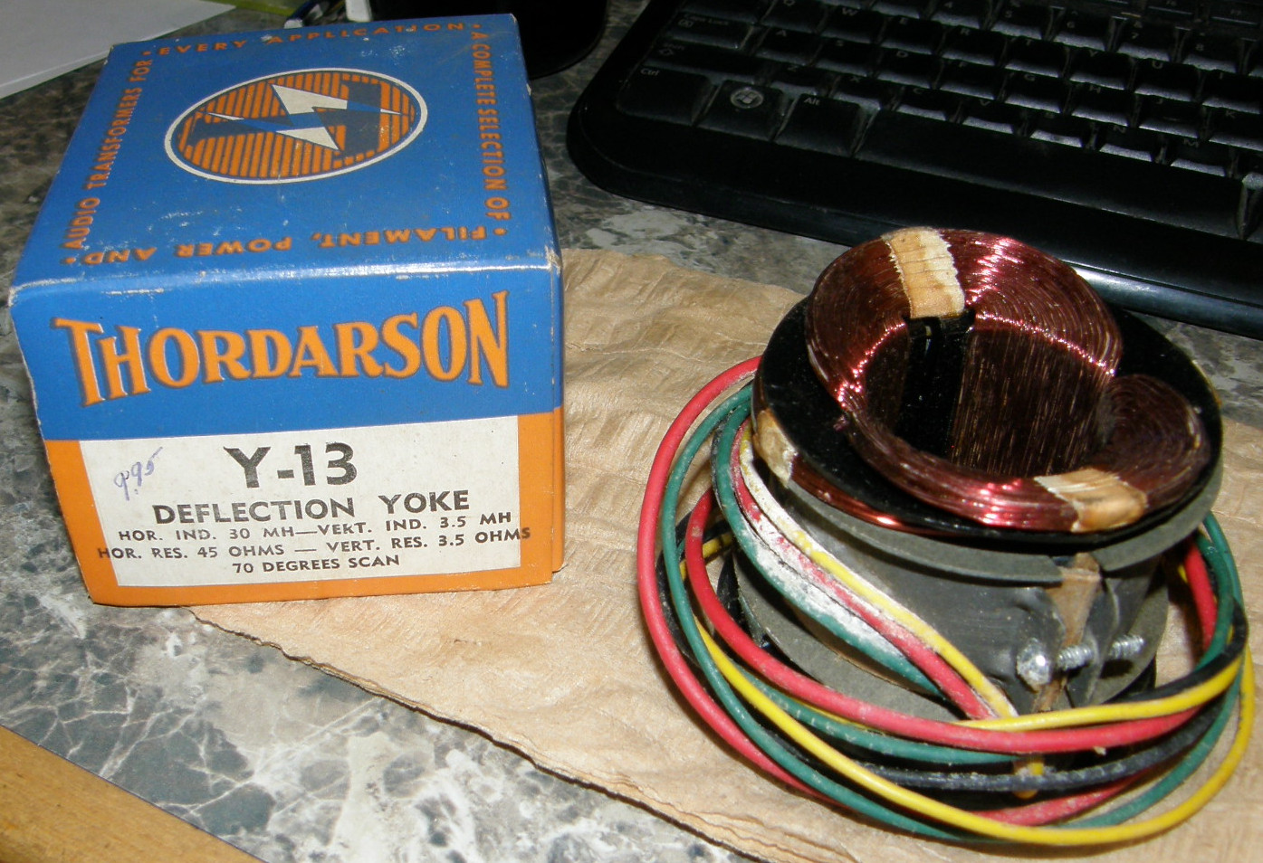
Forget everything I said before! It was AWL WORNG! - 20190316 And some people say they don't believe in evolution! It has been nearly three months since that last entry. I will not edit that out because the methods and techniques are valid despite the design being improved as the requirements changed over time. To bring you up to the present, a great deal of time was invested in developing and testing the deflection circuits. A couple of deflection yokes were tried that did not work out in the end. The deflection was more of a ball of hair than anticipated. With the assistance of several friends and colleagues, the problems were slowly solved, one after another. In the photos, above, the first one we see was the deflection yoke that was chosen and finally rejected. Details on the deflection page. The replacement is physically identical, but has electrical characteristics that were better suited to transistorized electronics. The Y-13 coils are essentially a pair of short circuits in this regard. A Thordarson Y-8 was ultimately selected and made functional. In the second photo above, the nearly finished deflection board undergoes final tests. In the end, with the help of my good friend, Howard Katz, this deflection board was good enough to consider The Chief to be actual functional test equipment! Though it is physically identical in its original form, the circuits went through a dozen evolutionary changes to reach this state of electronic perfection. Thanks Howie! You are a pal! 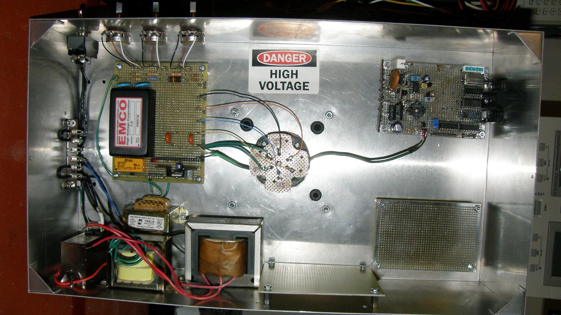
Finally, catching up to March 2019 As of March 16, 2019, this is the current state of The Chief's chassis interior. First thing of note is that the power supply has been changed to an entirely linear design using three separate iron core 60Hz transformers. The AC wiring is completed. The high voltage power supply, the deflection board, the future video output processor and the future low voltage power supply boards have been fitted to the case. One transformer is for the 2F21 monoscope heater filament. The large transformer is for the +/-12 volt, and lower voltages, needs. The bright yellow transformer will provide the voltage required for the horizontal deflection which requires a unique voltage between 30 and 40 volts DC, estimated. In the center of the photo, we see the bottom of the 3D printed, low insertion force, tube socket of my own design. The mechanism that supports the 2F21 / 1699 tubes, will allow for quickly changing monoscopes since I have more than one of them. As a bonus feature, The Chief can be used to test other 2F21 and 1699 monoscope tubes for my fellow tube collectors. The rest of the construction should now move very quickly as the hardest part of the design process has been completed. The low voltage power supplies will be very straight forward to construct. Then the video preamplifer, which will reside in the top end of the support frame will be developed and then, finally, the video output processor will be completed. 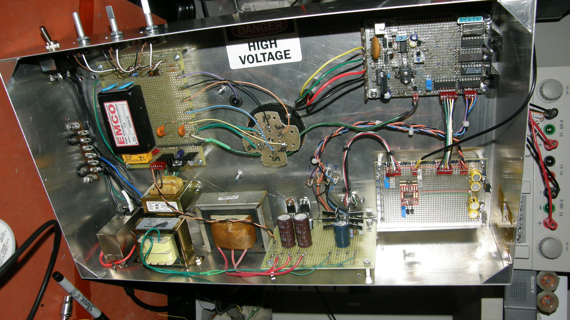
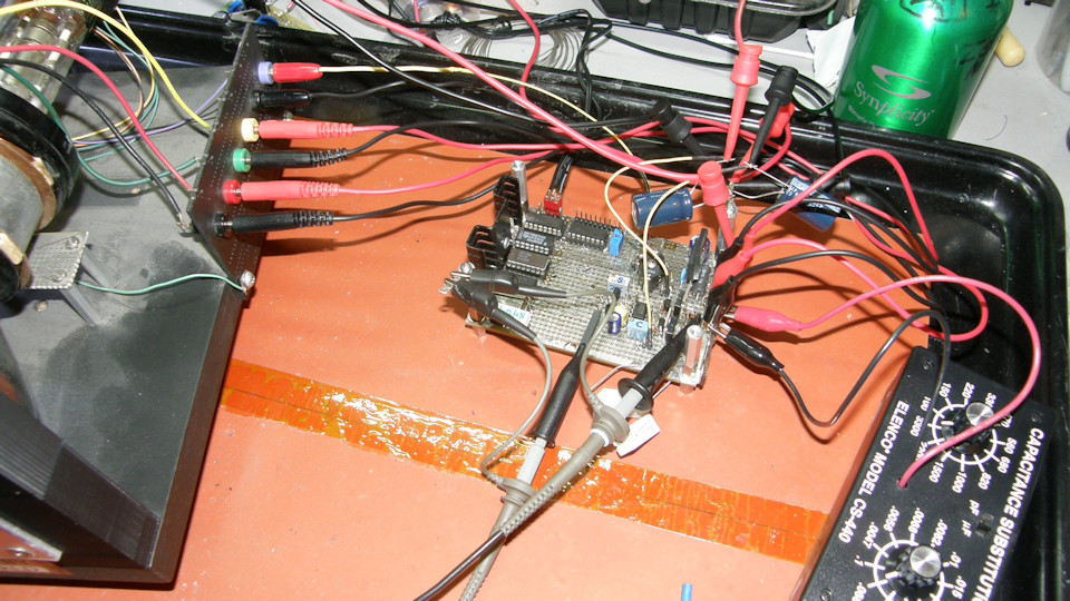
Progress as of April 2019 At this point, the low voltage power supplies are complete, the scan board and high voltage are operating nominally and video is being produced from the tube. Bad video. But, video none the less. As you can now clearly see, the wiring harness is evolving and has remained relatively neat in its routing and appearance. 
Video preamplifer housing and construction The video preamp threw a wrench in the plan because I foolishly thought I could route the output of the tube down a coax to the main video board. This turns out to be not true. This resulted in having to add another 3D printed part to the top of the support stack in which to contain the new video preamplifier. Inside this, I placed an aluminum canister which serves as the shielding for the very sensitive front end amplifier. This new assembly received the name of "the crown". 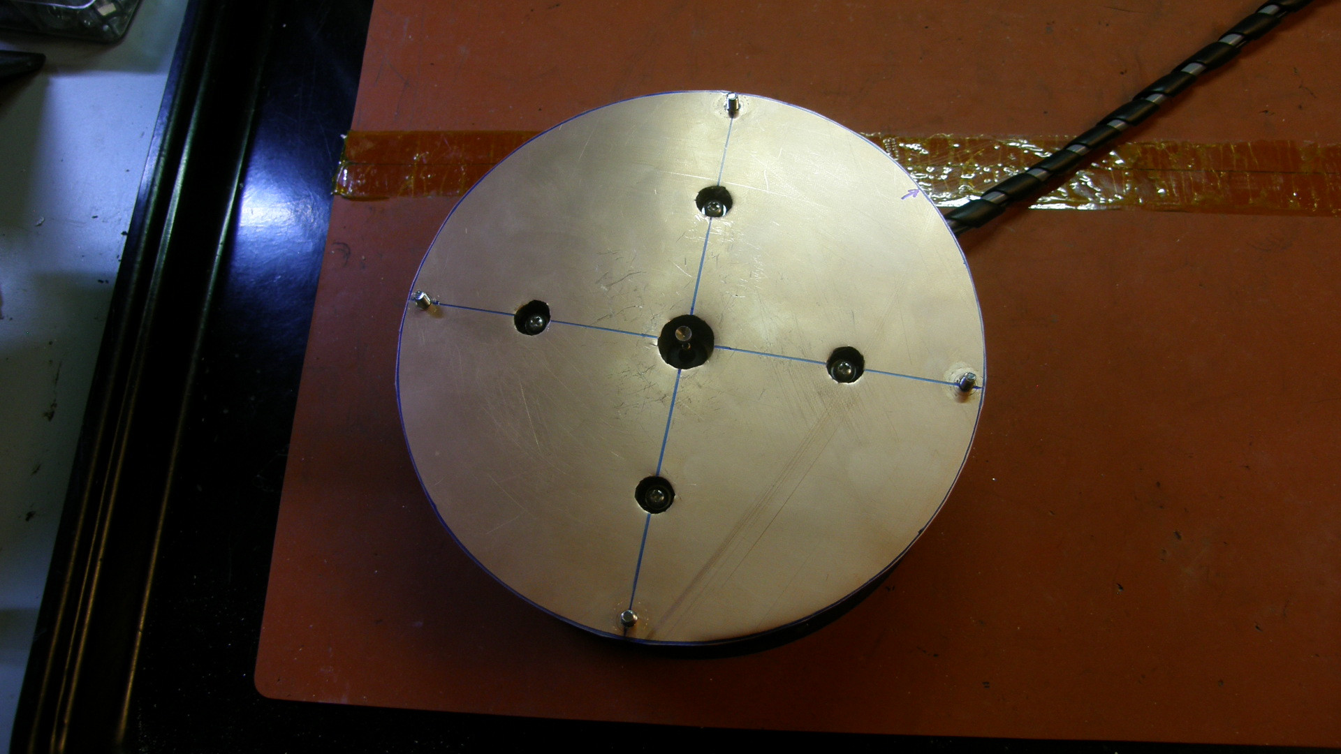
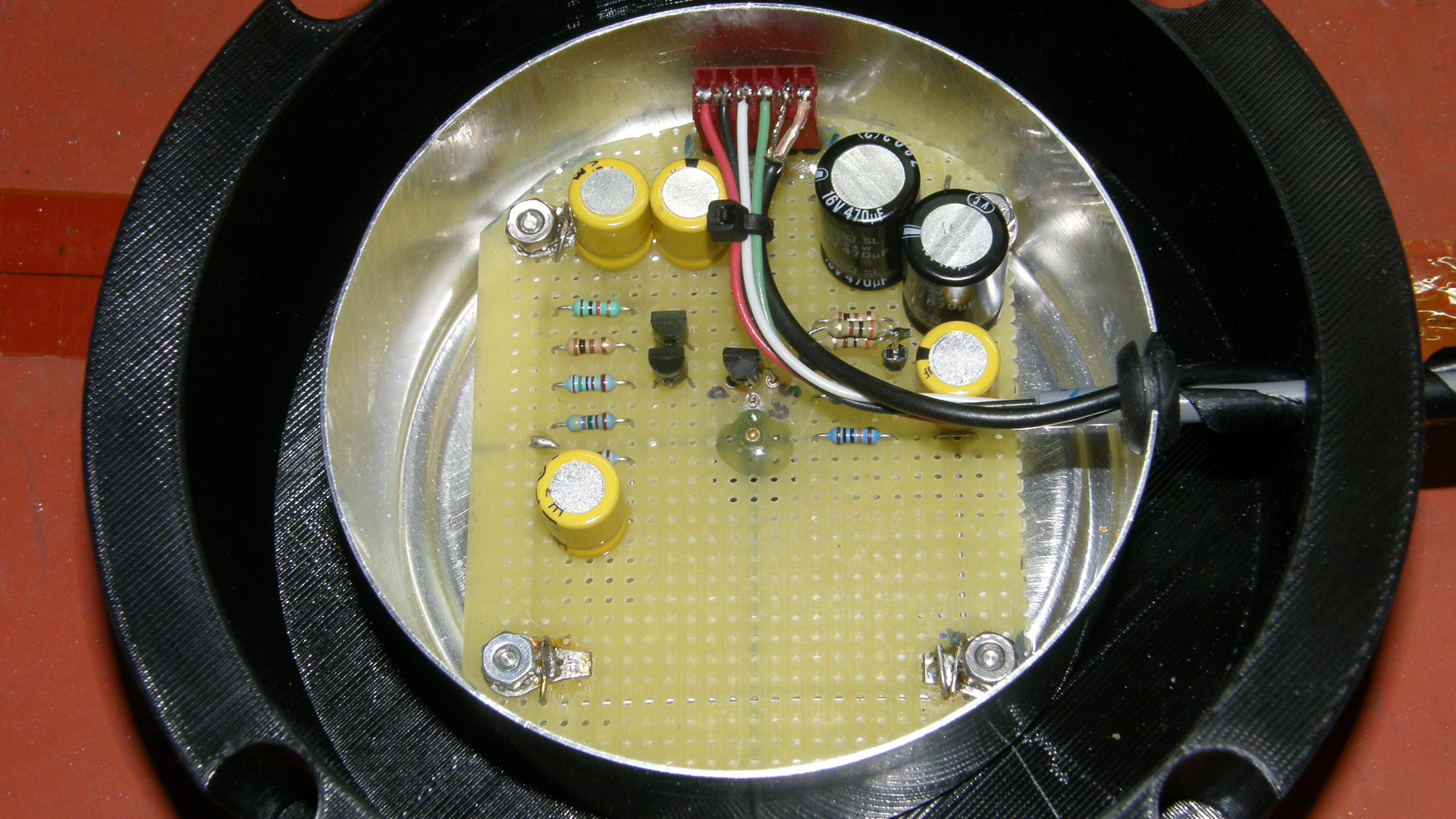
Video preamplifier bottom view and the crown's addition to the stack The can inside the crown and the faraday shield containing the monoscope tube are separately shielded and grounded to prevent any interference from the deflection system reaching the preamplifier. The crown did make the stack 52mm taller and extend above the copper can. Oh, well. We fixed that shortly thereafter. The contact to the front of the monoscope tube is by way of a spring loaded pogo pin that makes direct contact with PE contact of the tube. I'm rather proud of this small bit of mechanical engineering. The preamp in the crown is connected to the main chassis via a cable that is external to the shielded cylinder. Again protecting the precious video signal from deflection induced interference. 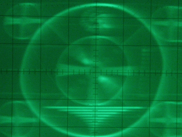
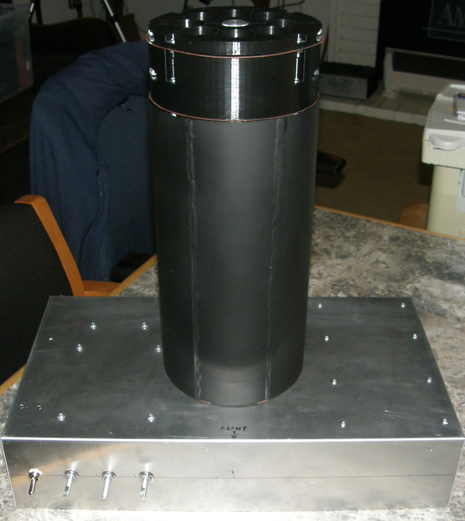
First image seen from the tube on the oscilloscope. The Chief gets formal. This was the moment we knew that the 2F21 tube was good. Of course, I immediately tested the 1699. Sadly, it produces no signal at all. But, realize this is quite an achievement and a moment of great joy! Moving on, I painted the copper cylinder black just to make it look sexy and to blend the crown which looked out of place sticking out the top of the copper tube! Kind of like a big Goth lip stick. Eeeew! Much better in all black. Way to go, Chief! 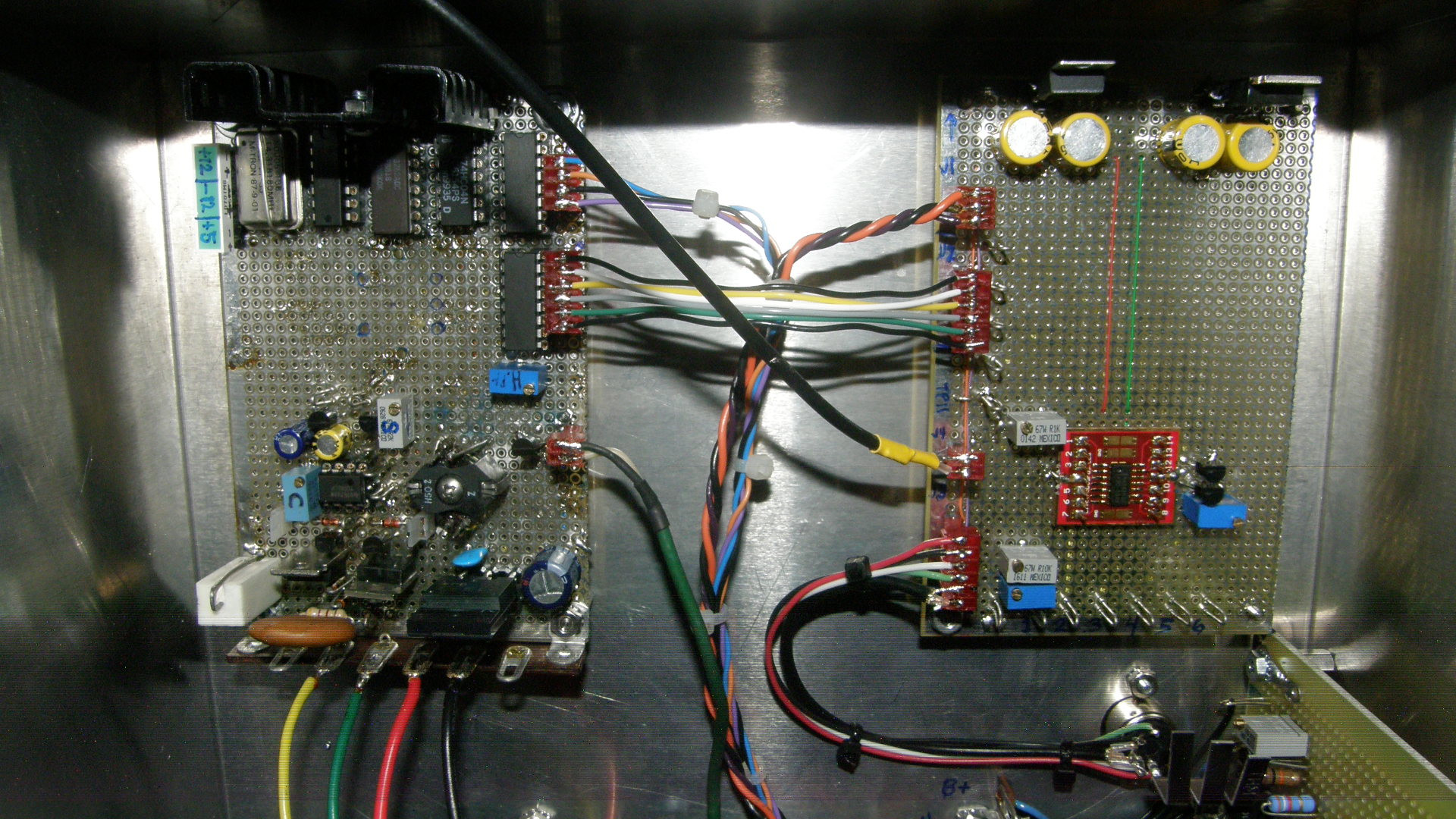
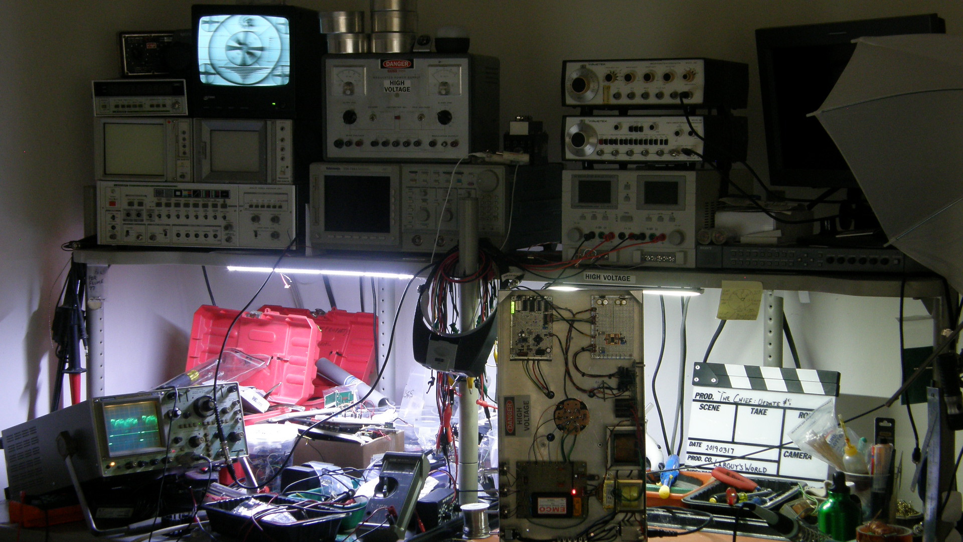
The final output board is functioning and the first TV picture is viewed in the lab! On the right of the first photo, is the video output processor board. It clamps the video, adds sync and compensates for some of the frequency roll off. In the second photo, the lab is looking good with those first images on the monitor. They sure look better from a distance than when viewed close up! There were frequency response issues that made the image very soft. But, this view gives the proper impression of the success felt at this point! 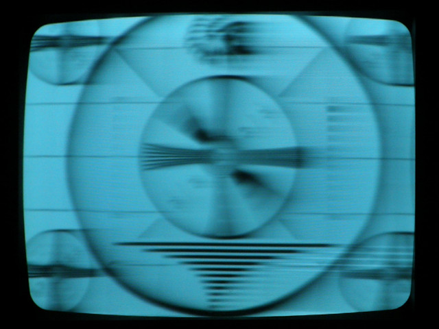
A closer look at the soft image on the CRT monitor. The Chief gets more pots. At this point, I was getting tired of flipping the chassis over every time I needed to adjust something. So, I brought out the four most common adjustments to the right side of the front panel. Those are Vertical Size, Vertical Centering, Horizontal Size and Horizontal Centering. The controls on the left side are the Off/Standby/On toggle switch, Beam, Focus, and Shading. Things are really starting to work better now. For all practical purposes, The Chief is now a fully functional monoscope tube tester! Of course, improvements will continue over time as with all of my projects. 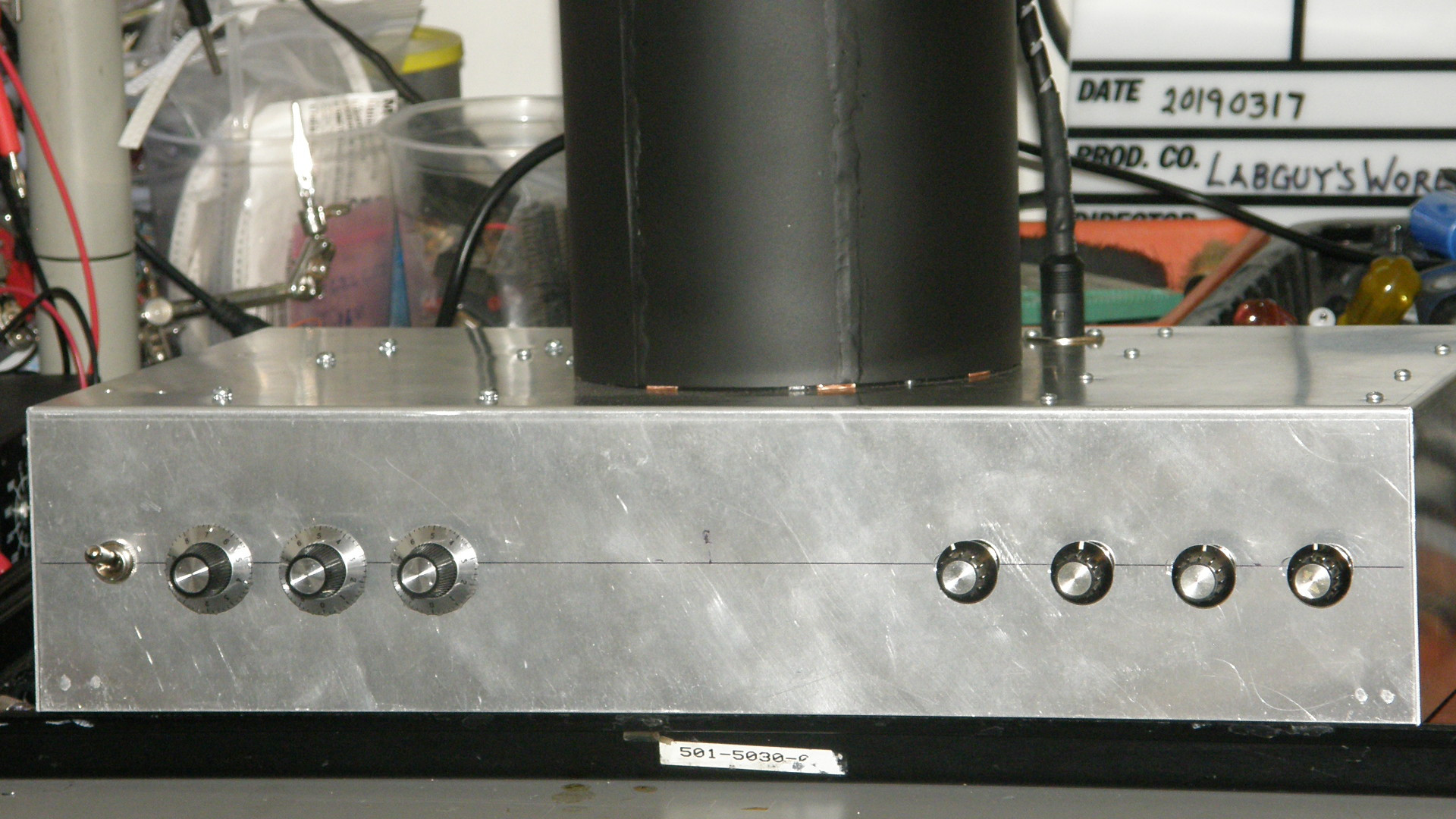
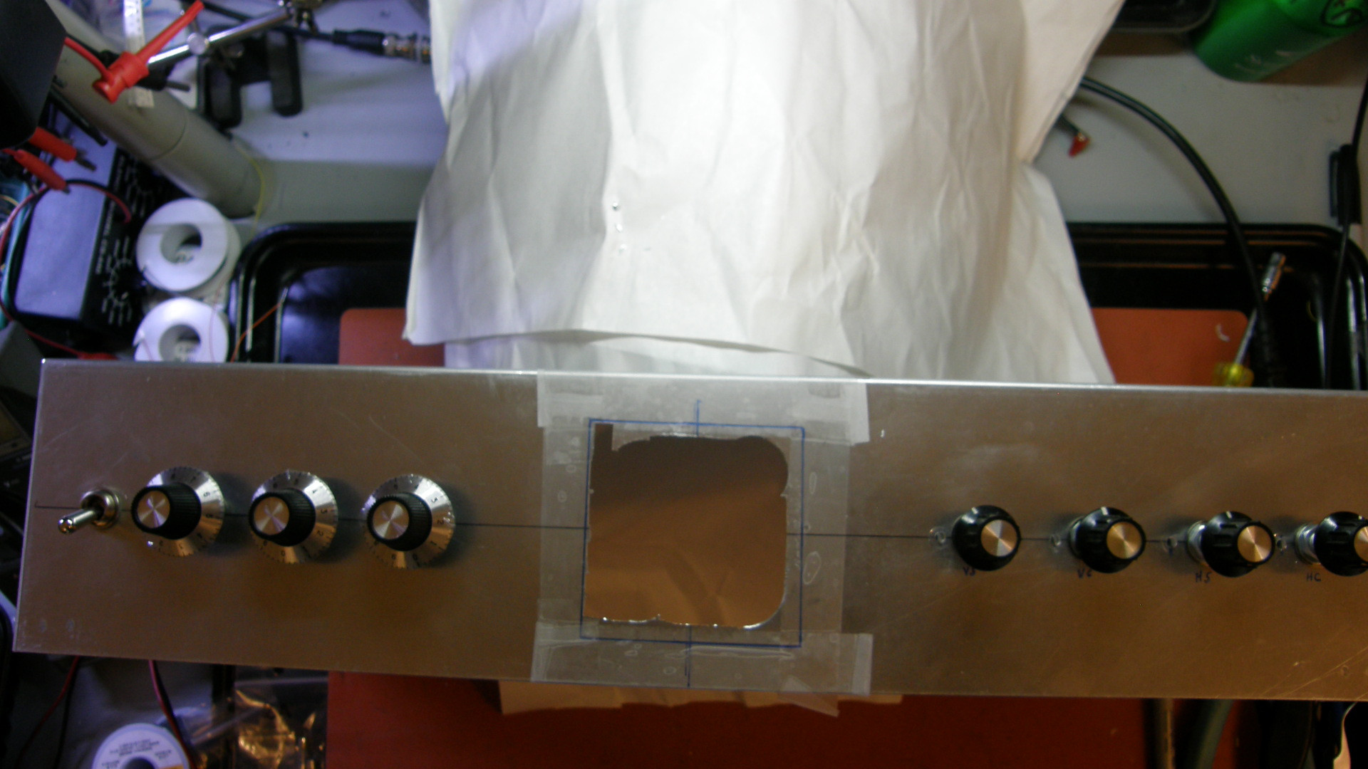
The Chief gets a set of knobs. Right hand photo: Labguy! WTF? Now it was time to integrate the art into the project. I'd been holding this close to the vest for a long time now. Had to chop a large 70x70mm hole right through the front center of the box. Lots of drilling. Working the nibbler and filing like the devil his self! Labguy actually worked up a sweat making this hole very very carefully. You can't put it back if you mess it up. All the work came out as fine as possible with hand work. Believe me, it was well worth it! 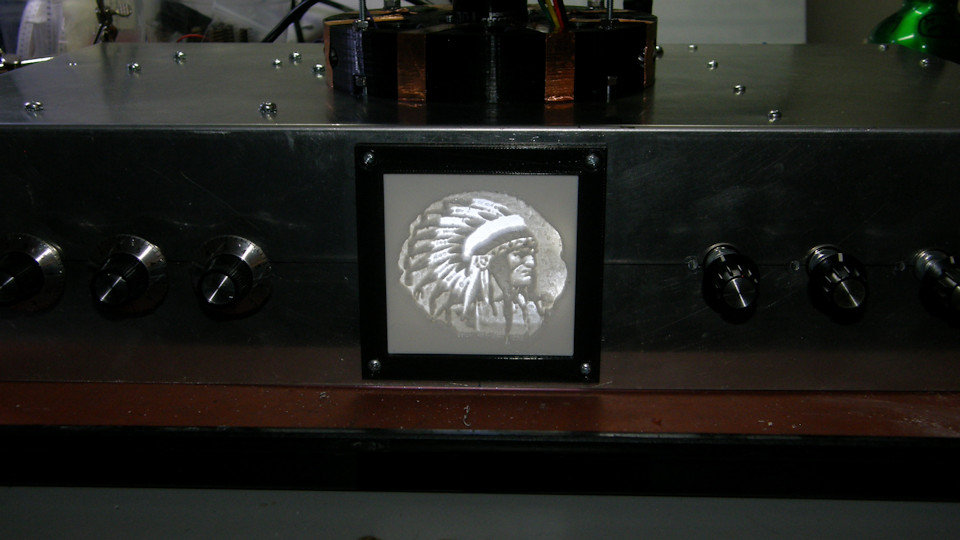
This is the fanciest pilot light any project has ever had! 20190407 The Chief LIVES! My Dad would have loved this! He loved his/our Native American heritage. (Our father was an officially registered member of the Paiute tribe. But, he messed up the paperwork for me and my brother, so the two of us are not officially registered. Therefore, to be perfectly clear, I am making no official claim to this heritage personally.) Have you ever heard of lithophane? Well, you have now! This is a method of producing a gray scale image by varying the thickness of a 3D printed object. Originally developed in China over a thousand years ago, artists would hand carve the inside of porcelain lamp chimneys with beautiful scenery. Only when the lamp was lit could this view be seen. Today, we can duplicate this effect with technology. When I stumbled on the lithophane page, it literally blew my mind! This was the cherry on top! It was the last dance! It was the shiznit! Make your own lithohpanes here: [Image To Lithophane]. 3D printing a nice black frame to wrap it all up was fun too. This lithophane of the very proud and handsome Indian Chief image is being dramatically lit from within the unit. Detail to follow. 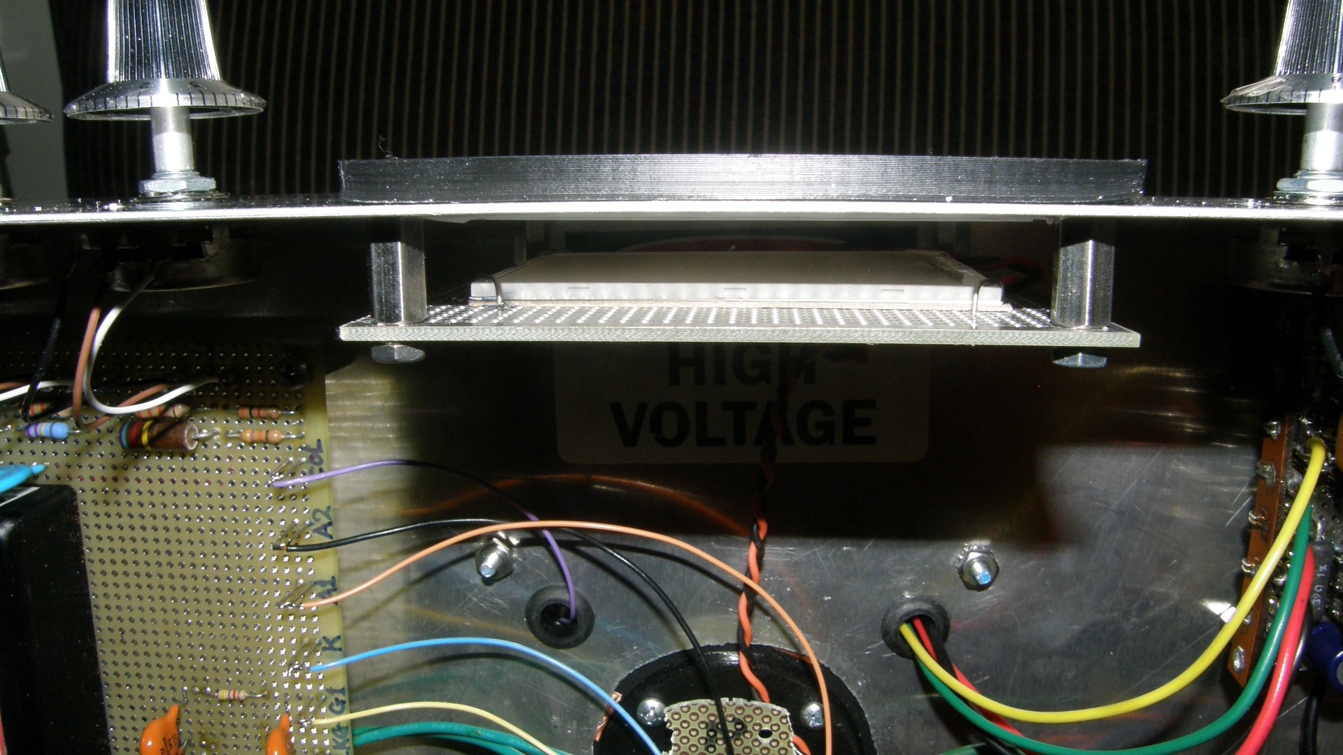
Internal detail of the lithophane back light assembly 20190414 The lithophane is illuminated by a small surplus LCD LED back light assembly. This operates on 9VDC which is provided by an LM7809 regulator mounted on the rear of the back light support PCB. The regulator is fed with regulated +12 volts so it does not have to dissipate so much heat energy. The ground plane of the PCB provides the heat sinking for the 9 volt regulator as well as an additional reflector for the light. The back light is held in place by four 20 gauge stiff copper wires folded over the corners and soldered to the PCB. The back light is insulated by a thin piece of cardboard paper salvaged from a depleted writing pad. (Labguy throws nothing away!) The entire lighting assembly is spaced from the front panel on four 3/8 inch long 4-40 threaded hermaphroditic stand offs. Easy peasey! Mechanical construction complete. Labguy can now add artist to his resume'. Let's move on to the various theories of operation of the various cuircuits and systems that make up the technology of The Chief. [HOME] [ELECTRONICS PROJECTS] [THE CHIEF TOP] [NEXT PAGE] |